System and method for beam focusing and control in an indirectly heated cathode

a technology of indirect heating and beam focusing, applied in the field of xray tubes, can solve the problems of shortening the life of filaments, affecting the quality of emission, and limited life of filaments, and evaporating the material of filaments

Inactive Publication Date: 2011-05-19
GENERAL ELECTRIC CO
View PDF7 Cites 16 Cited by
  • Summary
  • Abstract
  • Description
  • Claims
  • Application Information

AI Technical Summary

Problems solved by technology

Unfortunately, in these configurations, the filament has a limited life and low quality of emission especially for high power applications.
Further, high power applications call for the filament to be heated to a high temperature, which results in evaporation of material of the filament.
This evaporation of material in turn shortens the life of the filament.
This initial velocity lowers the beam quality and prevents the electron beam from forming a small size focal spot on the target.
This configuration unfortunately results in a non-uniform distribution of temperature at the emitter.

Method used


Image

  • System and method for beam focusing and control in an indirectly heated cathode
  • System and method for beam focusing and control in an indirectly heated cathode
  • System and method for beam focusing and control in an indirectly heated cathode

Examples


Embodiment Construction

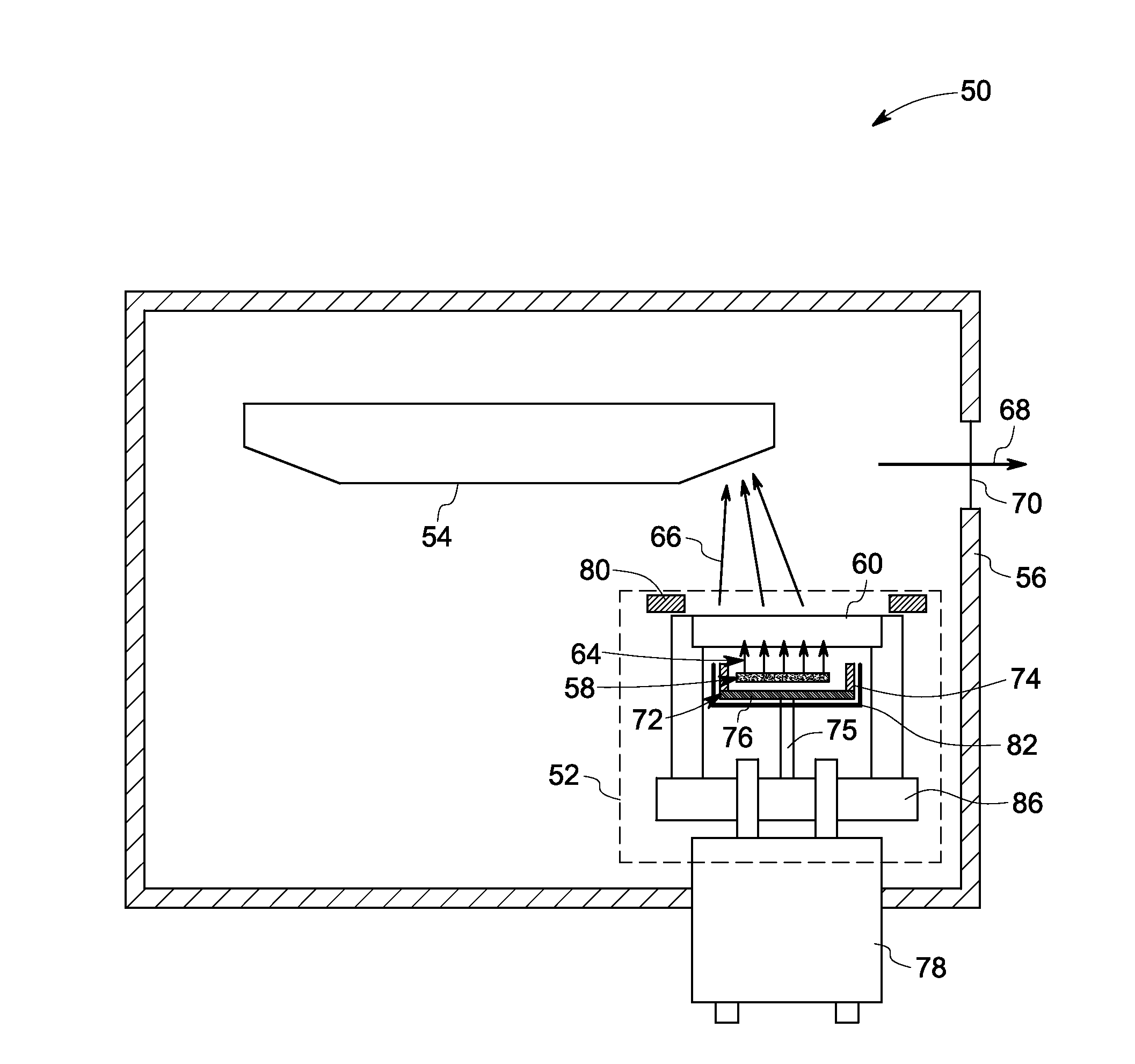
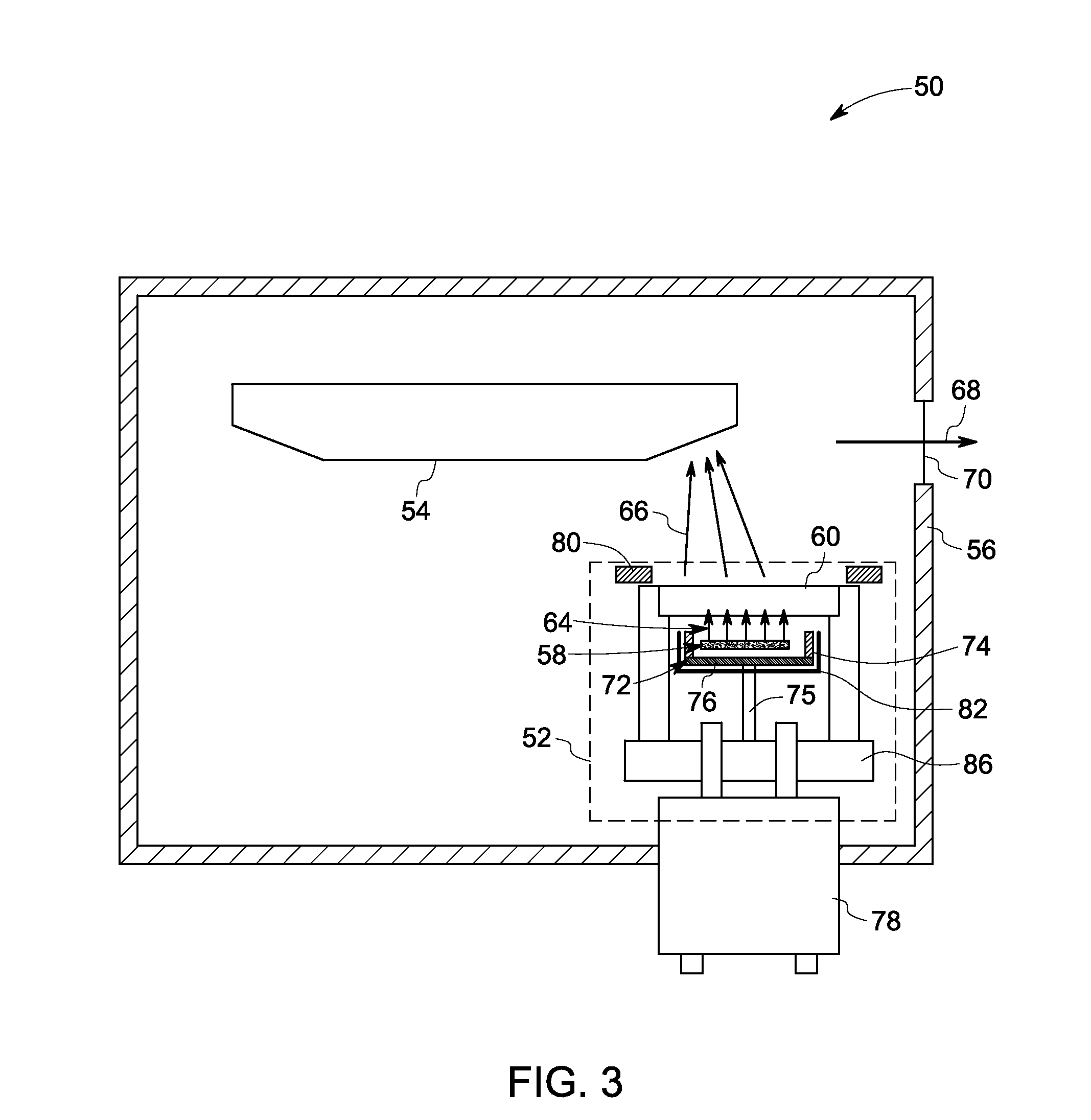
[0021]Embodiments of the present invention relate to a beam control mechanism for an indirectly heated cathode configured for use in an X-ray tube. An X-ray tube and a computed tomography system including the exemplary indirectly heated cathode assembly, as well as a method for beam focusing and controlling the electron beam in the indirectly heated cathode assembly are presented.

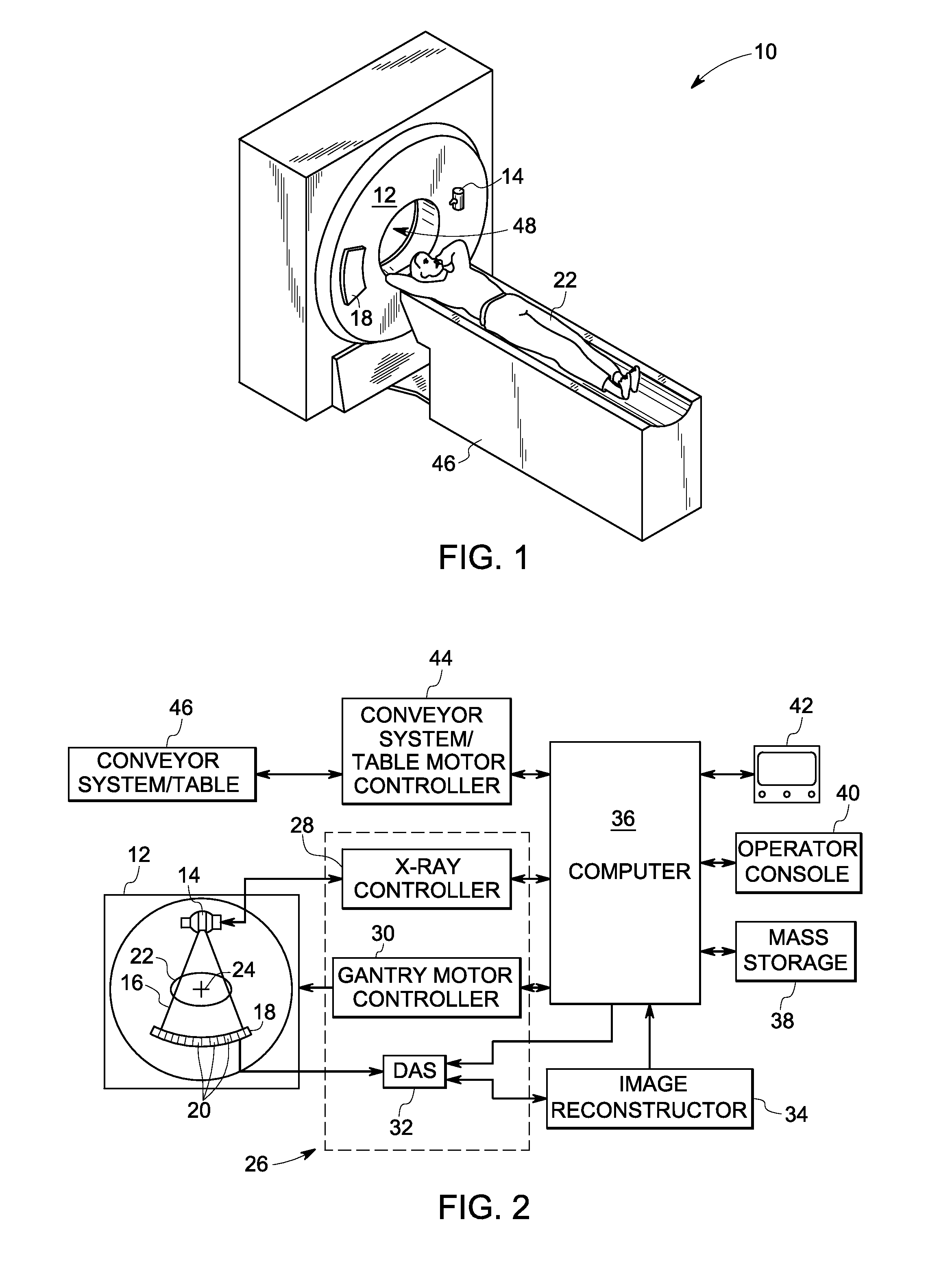
[0022]Referring now to FIGS. 1 and 2, a computed tomography (CT) imaging system 10 is illustrated. The CT imaging system 10 includes a gantry 12. The gantry 12 has an X-ray source 14, which typically is an X-ray tube that projects a beam of X-rays 16 towards a detector array 18 positioned opposite the X-ray tube on the gantry 12. In one embodiment, the gantry 12 may have multiple X-ray sources that project beams of X-rays. The detector array 18 is formed by a plurality of detectors 20 which together sense the projected X-rays that pass through an object to be imaged, such as a patient 22. During a scan to a...


PUM


Abstract

An indirectly heated cathode assembly is presented. The indirectly heated cathode assembly includes at least one electron source for generating a first electron beam, an emitter for producing a second electron beam when heated by the first electron beam and a focusing electrode for controlling, and directing the first electron beam towards the emitter.

Description

BACKGROUND[0001]Embodiments of the invention relate generally to X-ray tubes and more particularly to a method and apparatus for beam focusing and control in an indirectly heated cathode.[0002]Typically, in computed tomography (CT) imaging systems, an X-ray source emits a fan-shaped or cone-shaped beam toward a subject or an object, such as a patient or a piece of luggage. Hereinafter, the terms “subject” and “object” may be used to include anything that is capable of being imaged. The beam, after being attenuated by the subject, impinges upon an array of radiation detectors. The intensity of the attenuated beam radiation received at the detector array is typically dependent upon the attenuation of the X-ray beam by the subject. Each detector element of a detector array produces a separate electrical signal indicative of the attenuated beam received by each detector element. The electrical signals are transmitted to a data processing system for analysis. The data processing system p...

Claims


Application Information

Patent Timeline
Patent Type & Authority Applications(United States)
IPC IPC(8): H05G1/60H01J29/46H01J35/14
CPCH01J35/065H01J2235/167H01J2235/06H01J35/14H01J35/147
Inventor ZOU, YUNROBINSON, VANCE SCOTTINZINNA, LOUIS PAULCONWAY, KENNETH ROGERLEMAITRE, SERGIOFRONTERA, MARK ALANZHANG, XINECULAES, VASILE BOGDAN
Owner GENERAL ELECTRIC CO
Why Eureka
Try Eureka