Thermionic electron source

Active Publication Date: 2009-06-18
TSINGHUA UNIV +1
View PDF12 Cites 78 Cited by
  • Summary
  • Abstract
  • Description
  • Claims
  • Application Information

AI Technical Summary

Problems solved by technology

Furthermore, since the thermionic emitter adopting the boride or alkaline earth metal carbonate has high resistivity, the thermionic electron source using the same has greater power consumption and is therefore not su

Method used


Image

  • Thermionic electron source
  • Thermionic electron source
  • Thermionic electron source

Examples


Embodiment Construction

[0020]References will now be made to the drawings to describe, in detail, embodiments of the present thermionic electron source.

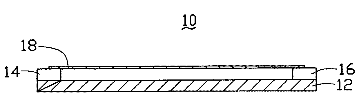
[0021]Referring to FIG. 1, a thermionic electron source 10, in accordance with a first embodiment, includes a substrate 12, a first electrode 14, a second electrode 16, and a thermionic emitter 18. The first electrode 14 and second electrode 16 are separately located on a surface of the substrate 12. The thermionic emitter 18 is located between the first electrode 14 and second electrode 16 and electrically connected thereto. The thermionic emitter 18 is suspended above the substrate 12 by the first electrode 14 and second electrode 16. The thermionic emitter 18 has a film structure.

[0022]The thermionic electron source 10 further includes a low-work-function layer (not shown) located on a surface of the thermionic emitter 18. The low-work-function layer is made of any material capable of inducing the emissions of electrons from the thermionic electron sourc...


PUM


Abstract

A thermionic electron source includes a substrate, at least two electrodes, and a thermionic emitter. The electrodes are electrically connected to the thermionic emitter. The thermionic emitter has a film structure. Wherein there a space is defined between the thermionic emitter and the substrate.

Description

RELATED APPLICATIONS[0001]This application is related to commonly-assigned applications entitled, “METHOD FOR MAKING THERMIONIC ELECTRON SOURCE”, filed ______ (Atty. Docket No. US18567); “THERMIONIC ELECTRON SOURCE”, filed ______ (Atty. Docket No. US18568); “THERMIONIC EMISSION DEVICE”, filed ______ (Atty. Docket No. US18570); “THERMIONIC EMISSION DEVICE”, filed ______ (Atty. Docket No. US18571); and “THERMIONIC ELECTRON EMISSION DEVICE AND METHOD FOR MAKING THE SAME”, filed ______ (Atty. Docket No. US18569).BACKGROUND[0002]1. Field of the Invention[0003]The present invention relates to a thermionic electron source adopting carbon nanotubes.[0004]2. Discussion of Related Art[0005]Carbon nanotubes (CNT) are a carbonaceous material and have received much interest since the early 1990s. Carbon nanotubes have interesting and potentially useful electrical and mechanical properties. Due to these and other properties, CNTs have become a significant contributor to the research and developme...

Claims


Application Information

Patent Timeline
IPC IPC(8): H01J21/10
CPCH01J1/14H01J2201/196H01J31/127
Inventor LIU, PENGLIU, LIANGJIANG, KAI-LIFAN, SHOU-SHAN
Owner TSINGHUA UNIV
Why Eureka
Try Eureka