Punched retainer, self-aligning roller bearing, and method of manufacturing punched retainer

a self-aligning roller bearing and retainer technology, applied in the direction of roller bearings, sliding contact bearings, mechanical equipment, etc., can solve the problems of difficult to form a structural portion that requires high precision over the entire circumference or in the circumferential direction using the flange, and difficult to apply uniform internal stress or uniform bending force. , to achieve the effect of high precision

Inactive Publication Date: 2011-05-19
NTN CORP
View PDF0 Cites 14 Cited by
  • Summary
  • Abstract
  • Description
  • Claims
  • Application Information

AI Technical Summary

Benefits of technology

[0015]Also, since the inner periphery of each pocket includes the punched section of the large-diameter annular portion, it is possible to form the bent portion of the flange at the large-diameter annular portion over the entire circumference. This makes it possible to make uniform the flatness of the back and front surfaces of the flange and its bent angle over the entire circumference.
[0016]According to the pre...

Problems solved by technology

Since it is difficult to apply uniform internal stress or uniform bending force to the respective connecting portions, the flange tends to be bent at the respective connecting portions t...

Method used


Image

  • Punched retainer, self-aligning roller bearing, and method of manufacturing punched retainer
  • Punched retainer, self-aligning roller bearing, and method of manufacturing punched retainer
  • Punched retainer, self-aligning roller bearing, and method of manufacturing punched retainer

Examples


first embodiment

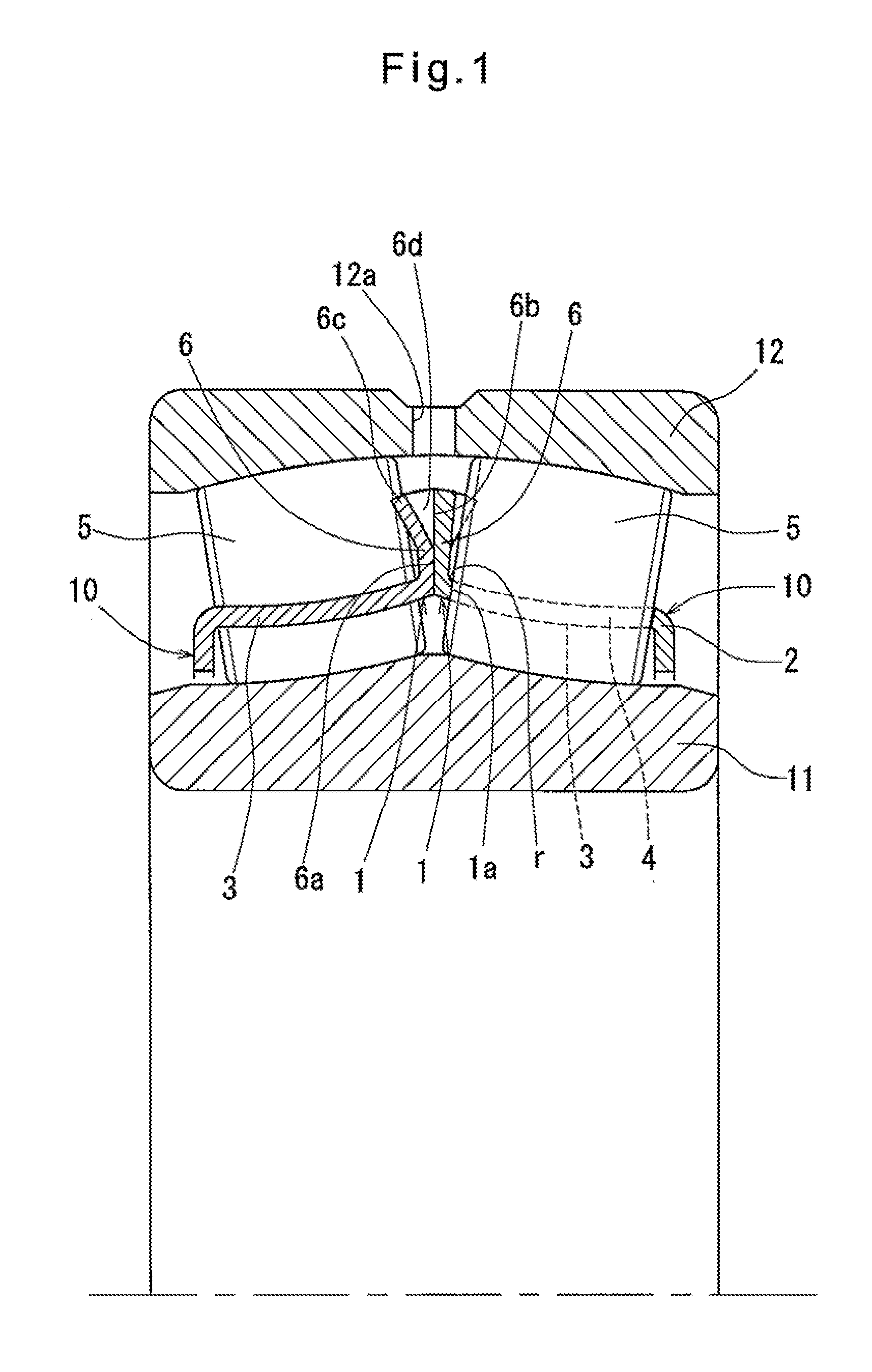
[0109]The self-aligning roller bearing does not include a guide ring disposed between the inner and outer races 11 and 12.

[0110]Since only with the opposed flat surface portions 6a and 6b, which are brought into sliding contact with each other, it is possible to prevent skew behavior of the punched retainers 10, it is possible to omit the guide ring and the intermediate flange, thus reducing the number of component parts of the self-aligning roller bearing and thus its cost.

[0111]Oil holes 12a are formed in the other of the inner and outer races (outer race 12 in the embodiment) through which lubricant is fed into the recesses 6d.

[0112]With the self-aligning roller bearing of the first embodiment, since the recesses 6d, which are formed when the anti-separation portions 6c are formed by bulging, extend to the distal edge of the flange 6, and are continuous with the flat surface portions 6a and 6b, and further, there are no guide ring, lubricant supplied through the oil holes 12a c...

second embodiment

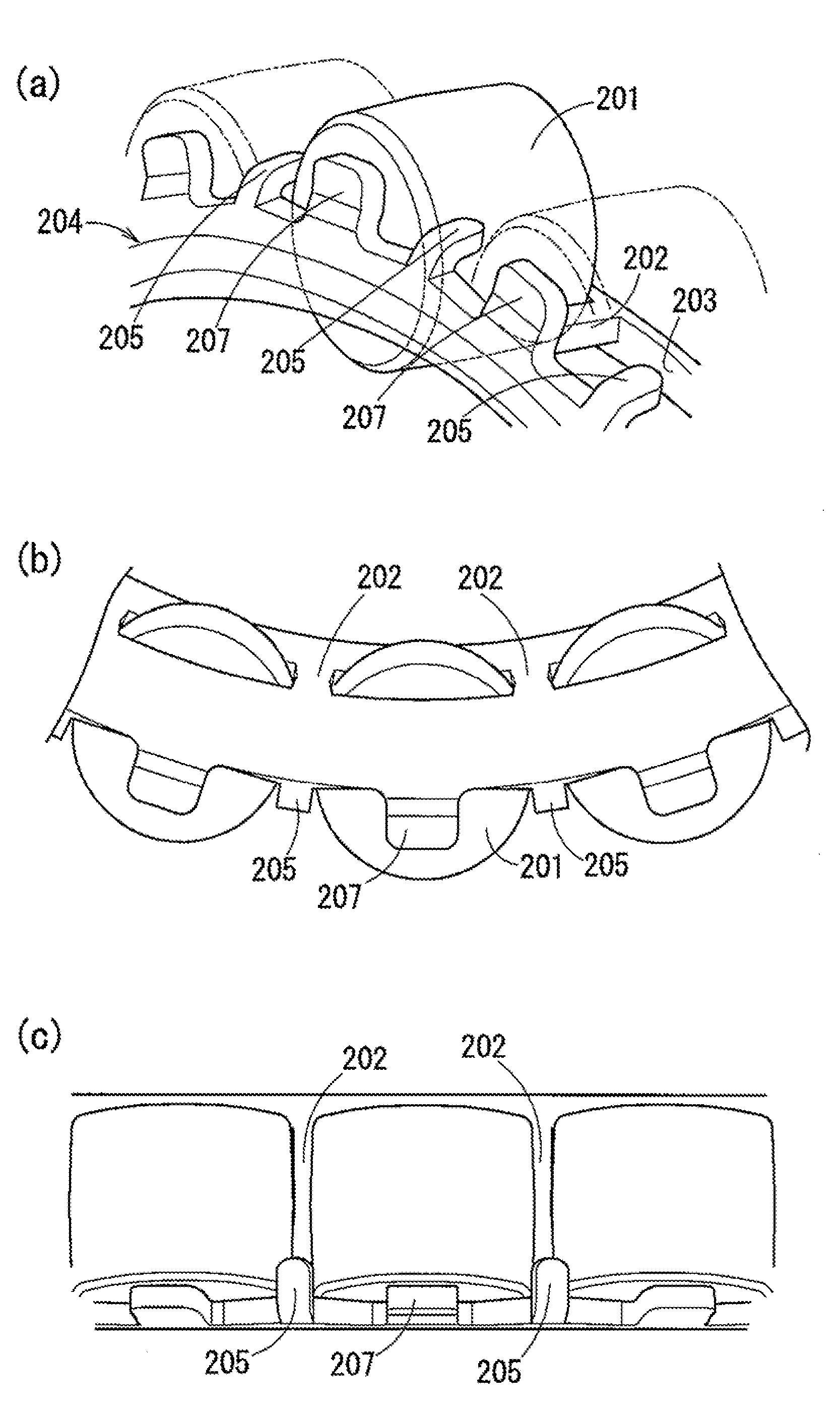
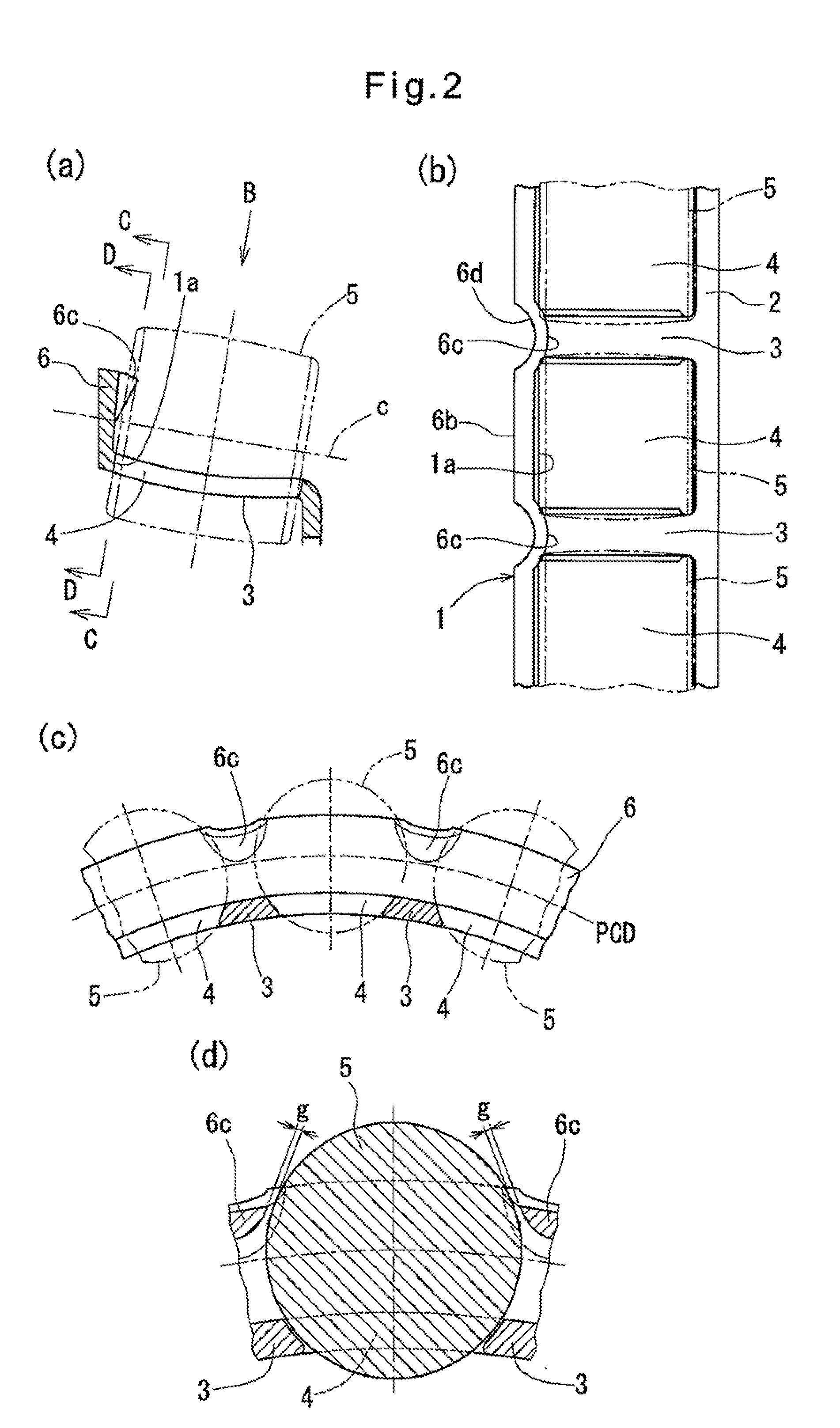
[0116]For example, in the second embodiment shown in FIGS. 9(a), 9(b), 10(a) and 10(b), bent pieces are formed that extend from the distal end of a flange 31, rollers guide surfaces 31a are formed by punching, and anti-separation portions 31b are formed by plastic deformation of the bent pieces. The portion between any adjacent anti-separation portions 31b is elastically expanded when the convex roller 5 is pushed in from the other of the radially inward and radially outward directions relative to the bridges 32 on both sides. Thus, the convex rollers 5 can be fitted in the respective pockets 33. Once the respective rollers are fitted in the pockets, the anti-separation portions 31b elastically recover and overlap the outer peripheral portions of the respective convex rollers 5 from the other of the radially inward and radially outward directions with a gap g.

[0117]If a recess is formed in one end surface of each convex roller, the anti-separation portions may be formed on the large...

third embodiment

[0138]As shown in FIG. 15, the punched retainers of the third embodiment may also be provided with roller guide surfaces 301a. Needless to say, the anti-separation portions comprising the bulges are provided irrespective of whether or not the roller guide surfaces 301a are formed.

[0139]In order to guide retainers of the self-aligning roller bearing with rollers, flat surface portions are formed on the backs of the respective flanges 314 which are brought into sliding contact with each other. On the front side of each flange 314, roller support surfaces 316 are formed for reducing skew behavior of the rollers 301.

[0140]By forming the roller support surfaces 316, the end surfaces of the rollers 301 in either row is prevented from being separated from the roller support surfaces 316, irrespective of the state of axial loads applied to the roller bearing. This stably prevents skew behavior of the rollers 30.

[0141]As shown in FIGS. 17(a), 17(b) and 19, the flat surface portion of the fla...


PUM

PropertyMeasurementUnit
Lengthaaaaaaaaaa
Angleaaaaaaaaaa
Diameteraaaaaaaaaa

Abstract

It is desired to form a flange and roller guide surfaces on each retainer of a self-aligning roller bearing easily and with high precision. Each punched retainer include a large-diameter annular portion (1), a small-diameter annular portion (2), a plurality of bridges (3) extending between the annular portions (1) and (2) and defining a plurality of circumferentially separated pockets (4) therebetween, roller guide surfaces (1a) that can be brought into sliding contact with end surfaces of respective convex rollers (5), which revolve around the axis of the bearing, and a flange (6) formed by radially bending the large-diameter annular portion (1). The roller guide surfaces (1a) comprise punched sections formed on the portions of the inner peripheries of the pockets (4) located at the large-diameter annular portion (1), and the flange (6) has a Bent Portion® that extends the entire circumference of the large-diameter annular portion (1). With this arrangement, the roller guide surfaces (1a) can be formed by punching only, which is a essential step. This makes it possible to make uniform the flatness of the back and front surfaces of the flange and its bent angle over the entire circumference thereof.

Description

TECHNICAL FIELD[0001]This invention relates to a punched retainer of which a flange and pockets are formed by pressing, a self-aligning roller bearing using such a punched retainer, and a method of manufacturing such a punched retainer.BACKGROUND ART[0002]A self-aligning rolling bearing is a double-row roller bearing of which the outer race is formed with a spherical raceway, and of which the rolling elements of the respective rows are convex rollers. In order to reduce skew behavior of the convex rollers when the rollers revolve around the axis of the bearing, the rollers are guided by a guide ring, an intermediate flange or a retainer. For example, Patent document 1 discloses a punched retainer formed with a guide surface that can be brought into sliding contact with the end surfaces of the revolving convex rollers.[0003]As shown in FIGS. 21(a) and 21(b), each punched retainer disclosed in Patent document 1 comprises a large-diameter annular portion 101, a small-diameter annular p...

Claims


Application Information

Patent Timeline
IPC IPC(8): F16C23/08F16C33/48B23P17/00
CPCF16C23/086Y10T29/49691F16C33/543F16C33/541F16C19/38
Inventor UMEMOTO, TAKEHIKOTSUMORI, YUKIHISAMAEDA, TAKESHISHIMIZU, YASUHIRO
Owner NTN CORP
Why Eureka
Try Eureka