Optical Network Interface Module Using a Hardware Programmable Optical Network Interface Engine

a technology of optical network interface and optical network module, which is applied in the direction of electromagnetic transceivers, multi-channel communication, digital transmission, etc., can solve the problems of adding to the cost of transceivers, adding to the complexity and cost of transceivers, and the transceivers typically cannot be programmed later by users

Active Publication Date: 2011-05-19
OE SOLUTIONS AMERICA
View PDF31 Cites 31 Cited by
  • Summary
  • Abstract
  • Description
  • Claims
  • Application Information

AI Technical Summary

Benefits of technology

[0013]The interface between the programmable ONI engine and the optoelectronic front-end allows the ONI engine to be used with different types of front-ends, including those that contain communication of both digital and analog signals. Similarly, the programmable ONI engine has an interface on the host module side that allows the ONI engine to be used with different types of host modules, which typically are digital. In this way, a single hardware programmable optical network interface engine can be used with different front-ends and host modules and to support different transport protocols and applications. An ONI engine can be used in transmitters, receivers, transceivers and / or transponders. One advantage of having a common engine that addresses many applications across a wide variety of markets is that manufacturing volumes can be high, thus driving down the cost.
[0014]In one embodiment, the programmable optical network interface engine supports burst mode transmission. This adds flexibility to the types of protocols and applications that can be supported since synchronous transmission is not required.

Problems solved by technology

These chip sets and the auxiliary chips to operate between the transceiver and other external subsystems add to the expense for any one application.
There is typically also a mixture of chips used for digital only and digital / analog functions, thus adding to the complexity and cost of the transceiver.
The transceiver typically cannot be programmed later by the user to implement a new or different protocol or interface to new or different optics.

Method used


Image

  • Optical Network Interface Module Using a Hardware Programmable Optical Network Interface Engine
  • Optical Network Interface Module Using a Hardware Programmable Optical Network Interface Engine
  • Optical Network Interface Module Using a Hardware Programmable Optical Network Interface Engine

Examples


Embodiment Construction

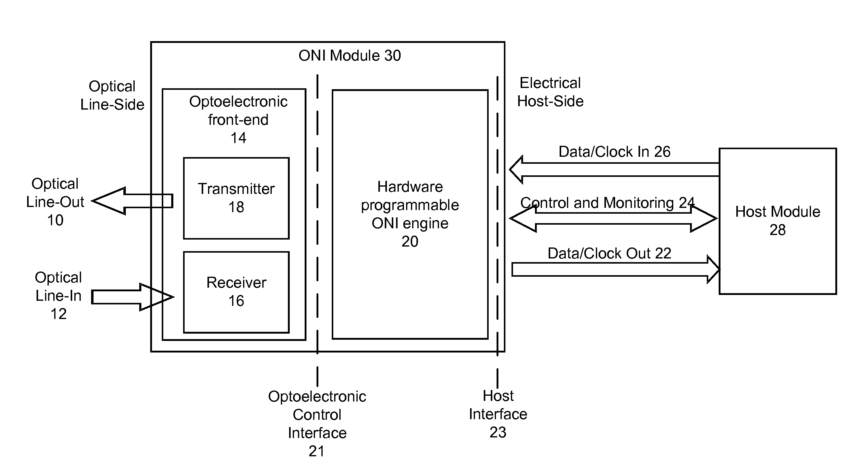
[0020]FIG. 1 is an architecture diagram of the present invention. The optical network interface module 30 includes an optoelectronic front-end 14 and a hardware programmable optical network interface engine 20. The optoelectronic front-end 14 includes a transmitter 18 and a receiver 16. The transmitter 18 and receiver 16 communicate with the optical data input 12 and optical data output 10 (i.e., the optical line-side). The ONI engine 20 implements physical (PHY) layer functions and, depending on the design, may also implement higher layer functions. The receive data path is from optical line-in 12 through receiver 16 and ONI engine 20 to electrical data-out 22. The transmit data path is from electrical data-in 26 through ONI engine 20 and transmitter 18 to optical line-out 10.

[0021]The ONI engine 20 interfaces to the optoelectronic front-end 14 on one side, and to host module 28 on the other side. The ONI engine 20 typically is implemented as a chip or chip set with associated firm...


PUM


Abstract

An optical network interface (ONI) module has two main components: an optoelectronic front-end and a general purpose hardware-programmable optical network interface engine. The ONI engine is hardware programmable, allowing the user to configure the overall ONI module with different optoelectronic front-ends and for use with different host modules. In this way, the ONI module can be configured for different applications and protocols.

Description

CROSS-REFERENCE TO RELATED APPLICATION(S)[0001]This application claims priority under 35 U.S.C. §119(e) to U.S. Provisional Patent Application Ser. No. 61 / 281,557, “Optical Burst Mode Clock and Data Recovery Method and Apparatus for Optical Transceivers,” filed Nov. 12, 2009 and to U.S. Provisional Patent Application Ser. No. 61 / 281,156, “Burst Mode Optical Transceivers with Embedded Electronic Application Specific Circuits (ASICs) and Application Specific Optics,” filed Nov. 12, 2009. The subject matter of all of the foregoing is incorporated herein by reference in their entirety.BACKGROUND OF THE INVENTION[0002]1. Field of the Invention[0003]This invention relates generally to fiber optic transceivers and transponders, and in particular to the use of an optical network interface engine that is hardware programmable to be used with different application-specific optoelectronic front-ends and / or different host modules and transport protocols.[0004]2. Description of the Related Art[0...

Claims


Application Information

Patent Timeline
Patent Type & Authority Applications(United States)
IPC IPC(8): H04J14/00
CPCH04B10/801H04L7/0075H04L7/027H04L7/0083H04B10/40H04B10/0793H04L65/1069
Inventor BLUMENTHAL, DANIEL J.POULSEN, HENRIK N.
Owner OE SOLUTIONS AMERICA
Why Eureka
Try Eureka