Systems and methods for endometrial ablation

a technology of endometrial ablation and system, applied in the field of electrosurgical methods and devices, can solve the problems of perforation or other damage of the uterine cavity

Active Publication Date: 2011-05-19
MINERVA SURGICAL
View PDF8 Cites 31 Cited by
  • Summary
  • Abstract
  • Description
  • Claims
  • Application Information

AI Technical Summary

Benefits of technology

[0014]In still more embodiments, a controller operated inflation source is provided in fluid communication with an inflation chamber of the balloon.
[0015]In still further embodiments, an indicator mechanism is provided for indicating a leak in the balloon. The i...

Problems solved by technology

The uterine cavity may be perforated or otherwise damaged by the tra...

Method used


Image

  • Systems and methods for endometrial ablation
  • Systems and methods for endometrial ablation
  • Systems and methods for endometrial ablation

Examples


Embodiment Construction

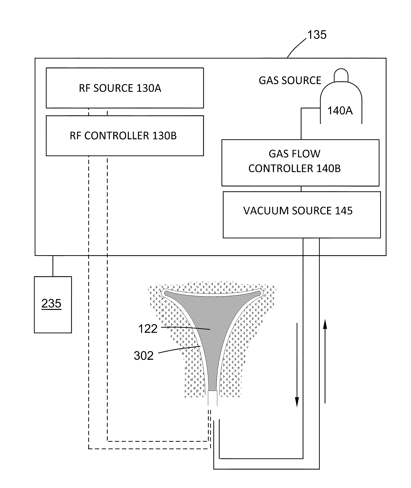
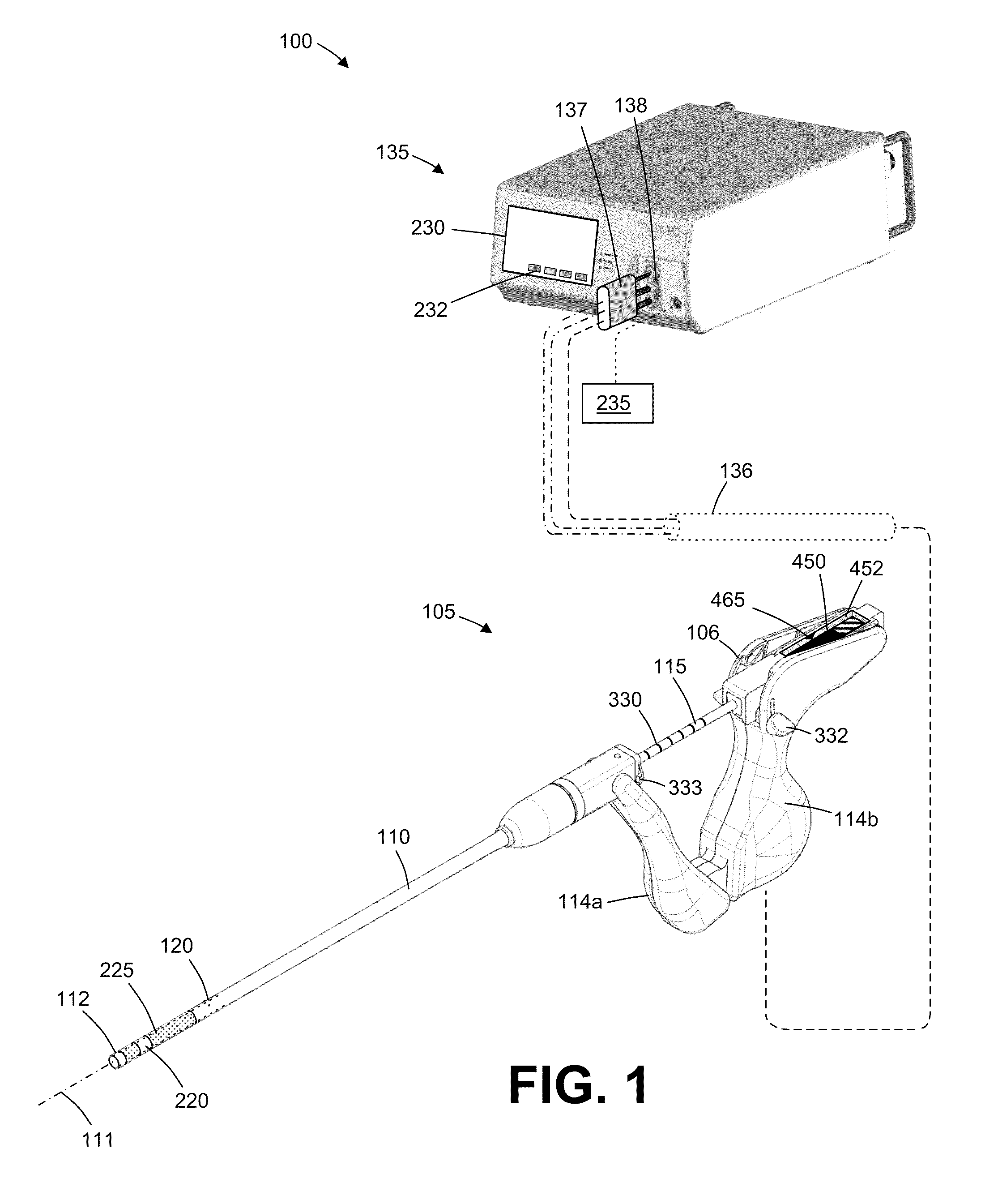
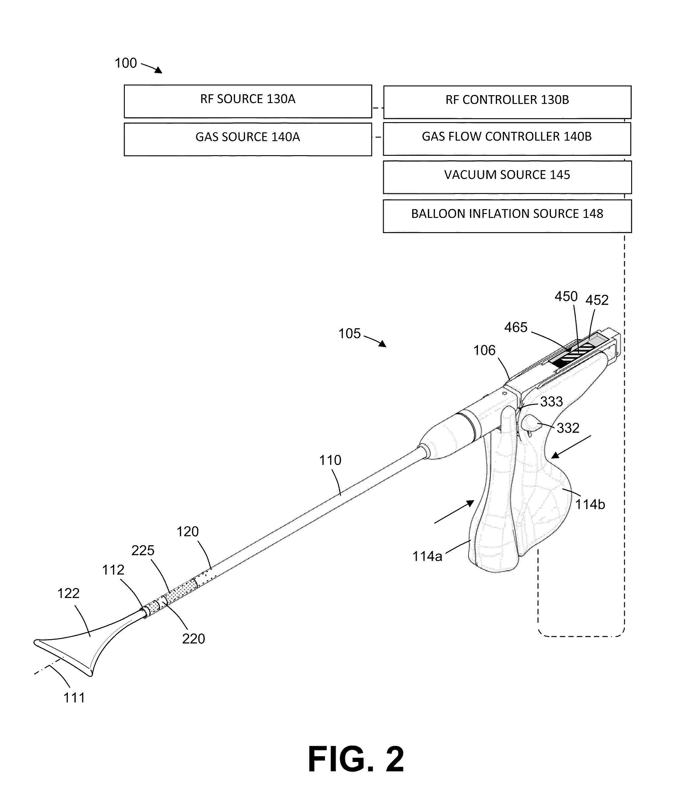
[0041]In general, an electrosurgical ablation system is described herein that comprises an elongated introducer member for accessing a patient's uterine cavity with a working end that deploys an expandable thin-wall dielectric structure containing an electrically non-conductive gas as a dielectric. In one embodiment, an interior chamber of the thin-wall dielectric structure contains a circulating neutral gas such as argon. An RF power source provides current that is coupled to the neutral gas flow by a first polarity electrode disposed within the interior chamber and a second polarity electrode at an exterior of the working end. The gas flow, which is converted to a conductive plasma by an electrode arrangement, functions as a switching mechanism that permits current flow to engaged endometrial tissue only when the voltage across the combination of the gas, the thin-wall dielectric structure and the engaged tissue reaches a threshold that causes capacitive coupling across the thin-w...


PUM


Abstract

Methods, systems and devices for endometrial ablation. In accordance with a method, a working end of an RF ablation device is positioned in a patient uterus to contact endometrial tissue, the working end comprising a dielectric wall capable of non-expanded and expanded shapes. An indicator mechanism is operatively coupled to the wall and configured to indicate non-expanded and expanded shapes of the wall. An expandable member, such as a balloon, is provided that expands to close the cervical canal during ablation.

Description

BACKGROUND[0001]1. Field of the Invention[0002]The present invention relates to electrosurgical methods and devices for global endometrial ablation in a treatment of menorrhagia. More particularly, the present invention relates to applying radiofrequency current to endometrial tissue by means of capacitively coupling the current through an expandable, thin-wall dielectric member enclosing an ionized gas.[0003]A variety of devices have been developed or proposed for endometrial ablation. Of relevance to the present invention, a variety of radiofrequency ablation devices have been proposed including solid electrodes, balloon electrodes, metalized fabric electrodes, and the like. While often effective, many of the prior electrode designs have suffered from one or more deficiencies, such as relatively slow treatment times, incomplete treatments, non-uniform ablation depths, and risk of injury to adjacent organs.[0004]For these reasons, it would be desirable to provide systems and method...

Claims


Application Information

Patent Timeline
IPC IPC(8): A61B18/18
CPCA61B18/042A61B18/1485A61B2017/00084A61B2017/22051A61B2017/4216A61B18/18A61B2018/00559A61B2018/00577A61B2018/00583A61B2018/00589A61B2018/1472A61B2018/00285
Inventor VISSY, LASZLOTOTH, AKOSHUNDERTMARK, RONALD
Owner MINERVA SURGICAL
Why Eureka
Try Eureka