Thermally actuated passive gas turbine engine compartment venting

a gas turbine engine and passive technology, applied in the direction of machines/engines, mechanical equipment, transportation and packaging, etc., can solve the problems of components and accessories in the core compartment being adversely affected, and the core compartment getting very ho

Active Publication Date: 2011-05-26
GENERAL ELECTRIC CO
View PDF31 Cites 52 Cited by
  • Summary
  • Abstract
  • Description
  • Claims
  • Application Information

AI Technical Summary

Problems solved by technology

The core compartment gets very hot during engine operation and the components and accessories therein may be adversely affected by overheating.

Method used


Image

  • Thermally actuated passive gas turbine engine compartment venting
  • Thermally actuated passive gas turbine engine compartment venting
  • Thermally actuated passive gas turbine engine compartment venting

Examples


Embodiment Construction

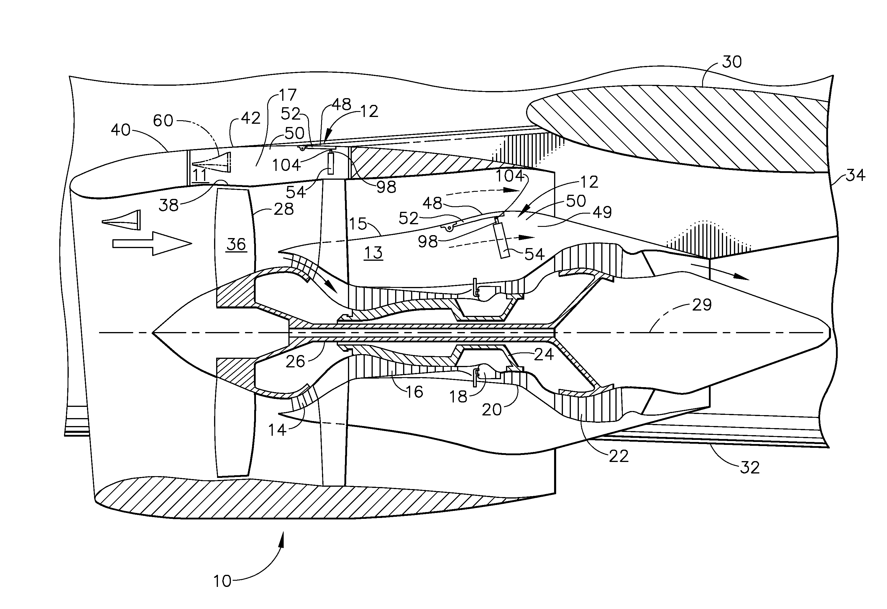
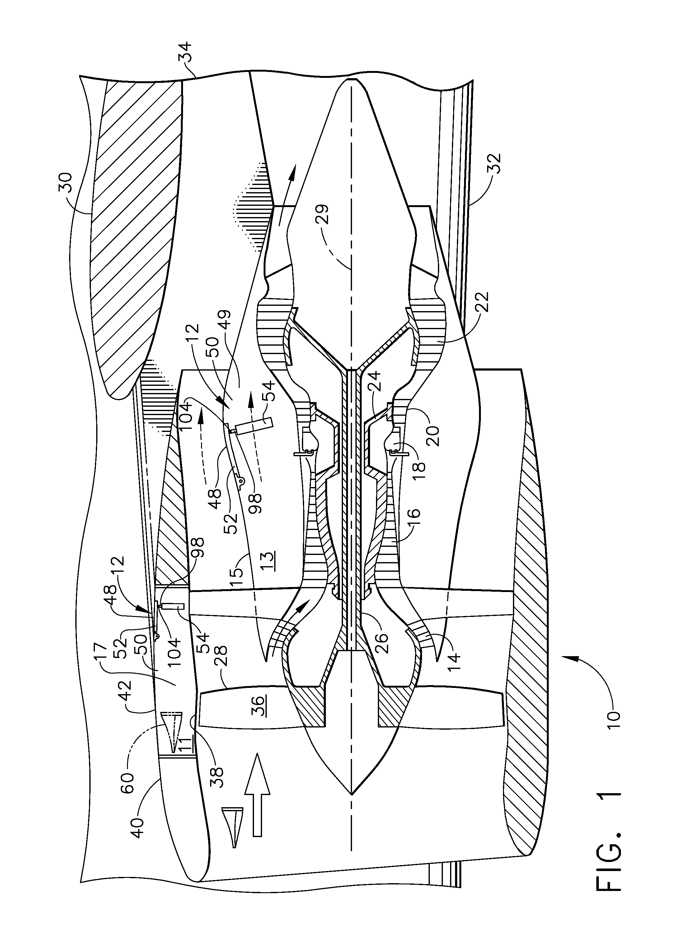
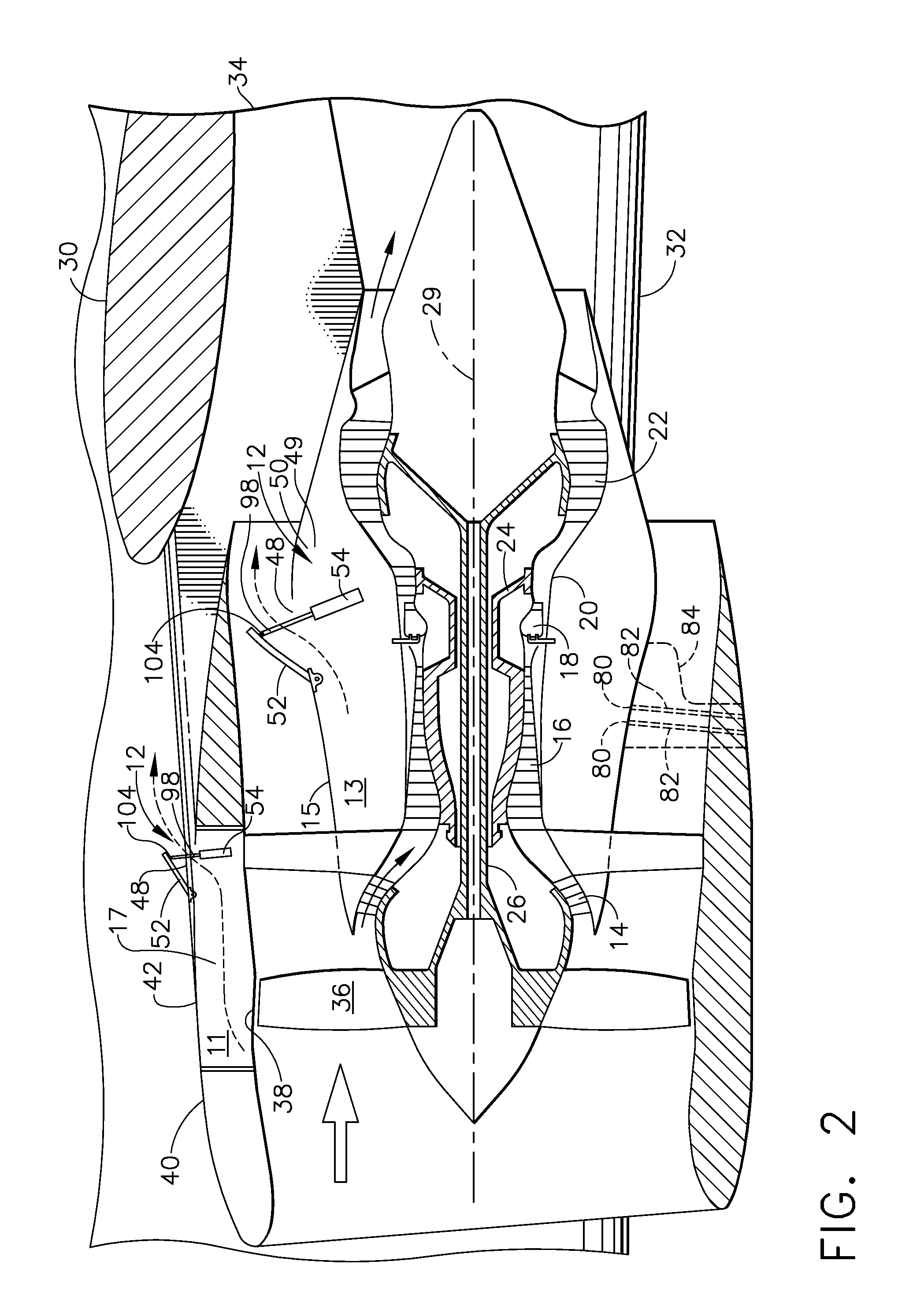
[0027]FIGS. 1 and 2 illustrate an exemplary turbofan gas turbine engine 10 incorporating thermally actuated venting systems 12 for venting a fan compartment 11 containing an electronic engine control 17 which may be a full authority digital electronic control (FADEC) and for venting a core engine compartment 13 circumscribed by a core engine cowl 15. FIGS. 3, 4, and 5 illustrate a pylon compartment thermally actuated venting systems 19 for venting a pylon compartment 21 containing an electronic engine control 17 which may be a full authority digital electronic control (FADEC). The thermally actuated cooling systems disclosed herein are illustrated for venting hot air from thus cooling down compartments associated with the engine 10 that are subject to heating due to soak back such as compartments inside an engine or its cowls or in a pylon 8 supporting the engine 10 above a wing 30 of an aircraft 6 illustrated in FIG. 11.

[0028]The exemplary engine 10 illustrated in FIGS. 1 and 2 inc...


PUM


Abstract

A thermally actuated venting system includes a thermally actuated vent for opening a vent outlet in a gas turbine engine associated compartment with a passive thermal actuator located in the compartment based on a temperature of the compartment. Outlet may be located at or near a top of a core engine compartment, a fan compartment, or a pylon compartment. Actuator may be operably connected to a hinged door of vent for opening outlet. Actuator may be actuated by a phase change material disposed in a chamber and having a liquid state below a predetermined actuation temperature and a gaseous state above the predetermined actuation temperature. Actuator may include a thermal fuse for closing door during a fire. Thermal fuse may include at least a portion of piston rod or a cylinder wall of actuator being made of a fuse material having a melting point substantially above the predetermined actuation temperature.

Description

BACKGROUND OF THE INVENTION[0001]1. Field of the Invention[0002]The present invention relates to cooling gas turbine engine compartments by venting and, more particularly, to venting hot air from gas turbine engine compartments subject to soak back when the engine is shut down.[0003]2. Description of Related Art[0004]Aircraft gas turbine engines have many compartments associated with the engine that are subject to heating due to soak back. The engines typically include a fan, a low pressure compressor, a high pressure compressor, a combustor, a high pressure turbine, and a low pressure turbine. The high pressure compressor, combustor, and high pressure turbine are collectively referred to as a core engine. An engine nacelle system for the engine extends circumferentially about the engine, sheltering the engine and providing aerodynamic surfaces which cooperate with the turbofan engine for generating thrust. A typical engine nacelle system includes a fan compartment surrounding a fan...

Claims


Application Information

Patent Timeline
Patent Type & Authority Applications(United States)
IPC IPC(8): F16P3/02
CPCB64D29/00B64D2033/024B64D2045/009F02K1/383F02K1/822Y02T50/672Y02T50/676F05D2270/09F05D2270/3032F05D2270/64F01D25/14F05D2260/20F05D2270/112Y02T50/60
Inventor DIAZ, CARLOS ENRIQUELABORIE, DANIEL JEAN-LOUISGEARY, STEPHEN DENNIS
Owner GENERAL ELECTRIC CO
Why Eureka
Try Eureka