Device and method for solar power generation

Active Publication Date: 2011-05-26
SUNPOWER CORPORATION
View PDF64 Cites 36 Cited by
  • Summary
  • Abstract
  • Description
  • Claims
  • Application Information

AI Technical Summary

Benefits of technology

[0006]The heat sink may form part of a photovoltaic assembly which is removably and replaceably mounted on the associated reflector element, the photovoltaic assembly further including the photovoltaic receptor and the mounting arrangement. By removable and

Problems solved by technology

The photovoltaic receptors forming part of such concentrators have a limited lifespan and the photovoltaic devices therefore require periodic removal and

Method used


Image

  • Device and method for solar power generation
  • Device and method for solar power generation
  • Device and method for solar power generation

Examples


Example

[0024]Example photovoltaic devices and solar power generation methods are described. In the following description, for purposes of explanation, numerous specific details are set forth in order to provide a thorough understanding of example embodiments. It will be evident, however, to one skilled in the art that the embodiments may be practiced without these specific details.

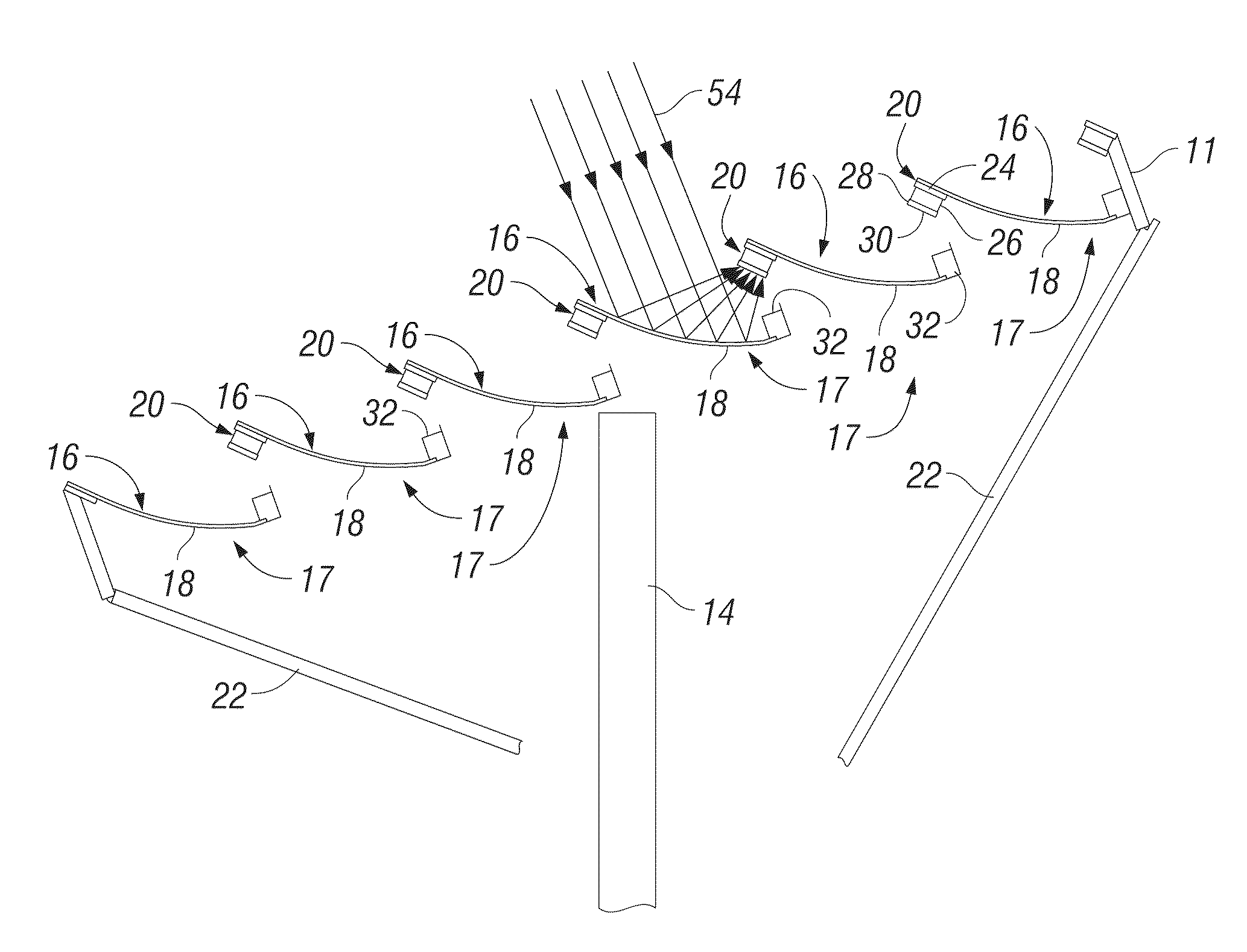
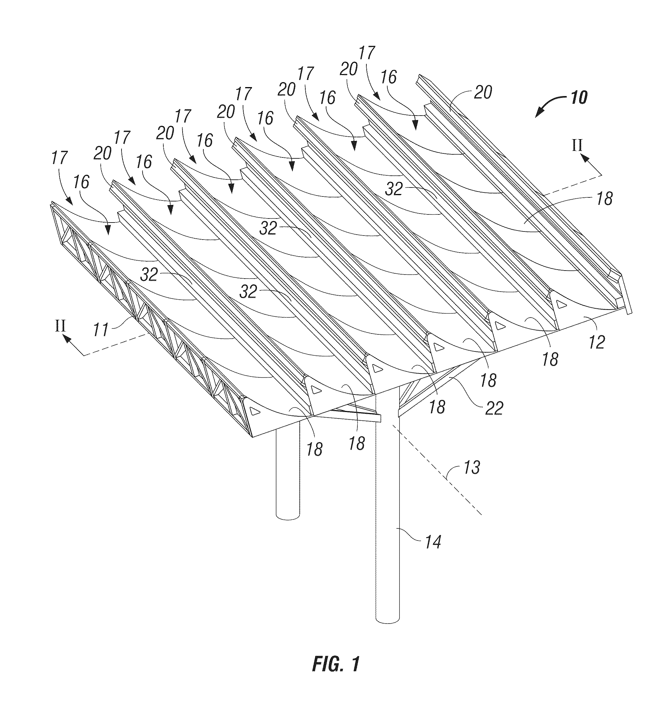
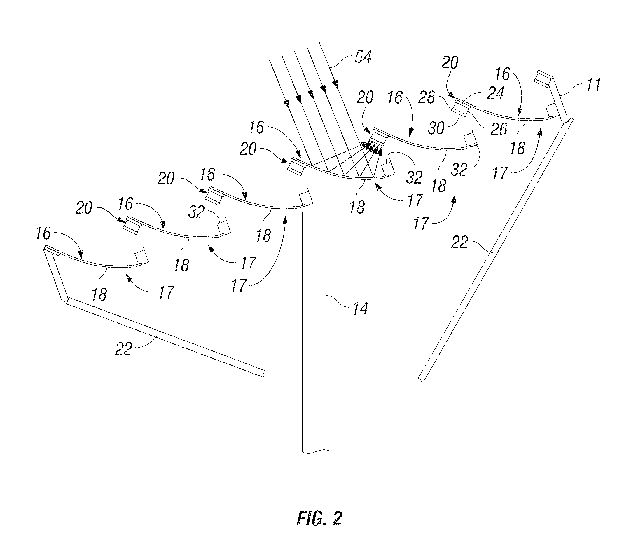
[0025]In the drawings, reference numeral 10 generally indicates a photovoltaic device in accordance with an example embodiment. As can be seen in FIG. 1 of the drawings, the device 10 is a slat concentrator comprising an array of reflector troughs or reflector elements 17 which are mounted on a rigid frame 11. The frame 11 is displaceably connected by struts 22 to an anchored support in the form of a pair of pylons 14. In particular, the frame 11 may be pivotally displaceable about an operatively horizontal axis 13 to permit tracking of the sun, in order to assist with optimal orientation of the reflector element...


PUM


Abstract

A photovoltaic device comprising an array of elongate reflector elements mounted substantially parallel to one another and transversely spaced in series, at least one of the reflector elements having an elongate concave reflective surface to reflect incident solar radiation towards a forward adjacent reflector element in the array. The at least one reflector element includes a photovoltaic assembly which is removably and replaceably mounted on the reflector element. The photovoltaic assembly includes a photovoltaic receptor to receive reflected solar radiation from a rearward adjacent reflector element. The photovoltaic assembly also includes a heat sink in heat transfer relationship with the photovoltaic receptor, thermally isolating the photovoltaic receptor, at least partially, from the reflector element.

Description

TECHNICAL FIELD[0001]The present application relates generally to the technical field of solar power generation, in one specific example, to a photovoltaic device. The application extends to a mounting unit and to a method of converting solar radiation to electrical power.BACKGROUND[0002]Various devices and systems are known for use in harvesting solar energy by the use of photovoltaic cells. These include slat concentrators, which are photovoltaic devices generally comprising a series of parallel trough-shaped off axis parabolic reflectors to concentrate sunlight on photovoltaic receptors mounted on respective adjacent reflectors. The reflectors are typically automatically actuated to track the sun in order to ensure accurate reflection and concentration of solar radiation on the photovoltaic receptors.[0003]The photovoltaic receptors forming part of such concentrators have a limited lifespan and the photovoltaic devices therefore require periodic removal and replacement of the pho...

Claims


Application Information

Patent Timeline
IPC IPC(8): H01L31/052F24S23/70F24S23/74
CPCF24J2/14F24J2/523F24J2/541F24J2002/1085H01L31/052H01L31/0522Y02E10/52H01L31/054H01L31/0525H01L31/0547Y02E10/47F24S23/74F24S25/10F24S30/425F24S2023/874H02S40/42H02S40/22
Inventor WARES, BRIANBARSUN, STEPHANDINWOODIE, TOM
Owner SUNPOWER CORPORATION
Why Eureka
Try Eureka