Pad clip for disc brake apparatus

Inactive Publication Date: 2011-05-26
AKEBONO BRAKE IND CO LTD
View PDF0 Cites 22 Cited by
  • Summary
  • Abstract
  • Description
  • Claims
  • Application Information

AI Technical Summary

Benefits of technology

[0008]The invention provides a pad clip for a disc brake apparatus which can stably provide a holding force and a close contact pro

Problems solved by technology

In any type of pad clip which obtains a holding force for the torque receiving portion in these manners, there is found a problem that it must be preven

Method used


Image

  • Pad clip for disc brake apparatus
  • Pad clip for disc brake apparatus
  • Pad clip for disc brake apparatus

Examples


first embodiment

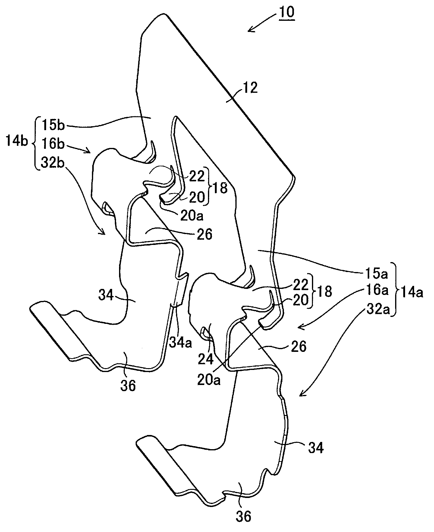
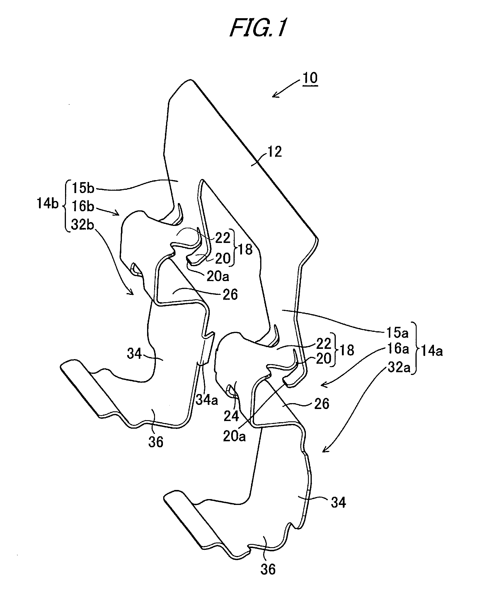
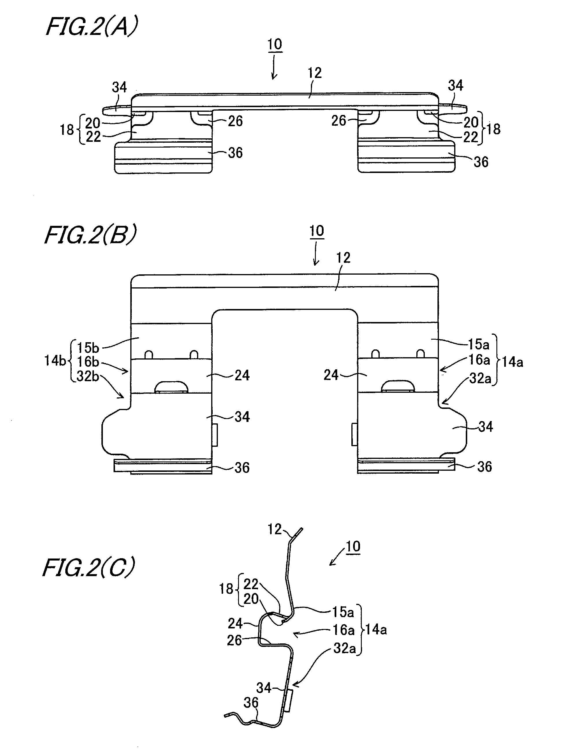
[0049]Next, description will be given below of a first embodiment (a basic mode) of a pad clip according to the invention. Here, FIG. 1 is a perspective view of a pad clip according to the first embodiment. Also, FIG. 2(A) is a top plan view of the pad clip, FIG. 2(B) is a front view of the pad clip, and FIG. 2(C) is a right side view of the pad clip, respectively. Referring to the structure of a pad clip 10 according to the first embodiment, two leg portions 14a and 14b, which are respectively disposed in the inner side torque receiving portions 52a, 52b and in the outer side torque receiving portions 52c, 52d, are unified together by a bridge portion 12. A material of the pad clip 10 may be a stainless steel plate or a rust prevention treated steel plate; and, to form the pad clip 10, a member cut into a flat plate may be bent formed.

[0050]The leg portions 14a and 14b respectively include leg portion base end portions 15a, 15b, sandwiching portions 16a, 16b, and pad hold portions ...

second embodiment

[0069]Next, description will be given below of a second embodiment (a basic mode thereof) of a pad clip for a disc brake apparatus according to the invention with reference to FIGS. 9(A) and 9(B). FIG. 9(A) is a perspective view of a pad clip according to the second embodiment, while FIG. 9(B) is a side view of the pad clip according to the second embodiment, showing a state where it is mounted on a torque receiving portion. Also, the pad clip according to the second embodiment is substantially similar in structure to the pad clip according to the previously described first embodiment. Therefore, to the composing elements of the second embodiment which are similar in function to those of the first embodiment, there are given reference numerals which can be obtained by adding 100 to the reference numerals of the first embodiment; and thus, the detailed description thereof is omitted here. Here, in the case of the torque receiving portion of the support member, there can be used a sim...

third embodiment

[0084]Next, description will be given below of a third embodiment of a pad clip for a disc brake apparatus according to the invention with reference to FIGS. 18(A) and 18(B). FIG. 18(A) is a perspective view of a pad clip according to the third embodiment, while FIG. 18(B) is a partially enlarged view of the pad clip according to the third embodiment, showing a state where it is mounted on the torque receiving portion of a support member. Also, the pad clip according to the third embodiment is substantially the same in structure as the pad clip according to the previously described first embodiment. Therefore, the composing elements of the third embodiment having the same functions as those of the first embodiment are given reference numerals in which 200 are added to the reference numerals of the first embodiment, and thus the detailed description thereof is omitted here. Also, in the case of the torque receiving portion of the support member, since there can be used a similar port...


PUM


Abstract

A pad clip for a disc brake apparatus is provided with a sandwiching portion for sandwiching a projecting portion formed in a support member of the disc brake apparatus. The sandwiching portion includes an upper hold piece, a lower hold piece, and a connecting piece for connecting the upper hold piece and lower hold piece to each other. The upper hold piece includes a hold claw having a leading end urged toward an upper surface of the projecting portion and in contact with a vertically extending wall surface of a recessed groove formed in the projecting portion, and a spring piece for urging the hold claw. When the sandwiching portion sandwiches the projecting portion, the spring piece is not in contact with the upper surface of the projecting portion.

Description

TECHNICAL FIELD[0001]The present invention relates to a pad clip for use in a disc brake apparatus, and specifically relates to a pad clip of a type which is used to sandwich a projecting portion formed in a support member.BACKGROUND ART[0002]As a pad clip for a disc brake apparatus, there are known a pad clip of a type which is used to sandwich a projecting portion formed in a torque receiving portion of a support member or the like; and, a pad clip of a type in which there is formed a recessed portion in the torque receiving portion and the pad clip is spread and held in the recessed portion. In any type of pad clip which obtains a holding force for the torque receiving portion in these manners, there is found a problem that it must be prevented from being removed from the torque receiving portion and must be enhanced in its close contact property with respect to the torque receiving portion.[0003]In Patent Document 1, there is disclosed a method for solving the above problem. In ...

Claims


Application Information

Patent Timeline
IPC IPC(8): F16D65/12
CPCF16D65/0977F16D65/0972
Inventor SHIMAMURA, KENICHI
Owner AKEBONO BRAKE IND CO LTD
Why Eureka
Try Eureka