

Truss-shaped engine pylon and method of making same
- Summary
- Abstract
- Description
- Claims
- Application Information
AI Technical Summary
Benefits of technology
Problems solved by technology
Method used
Image

Examples
first embodiment
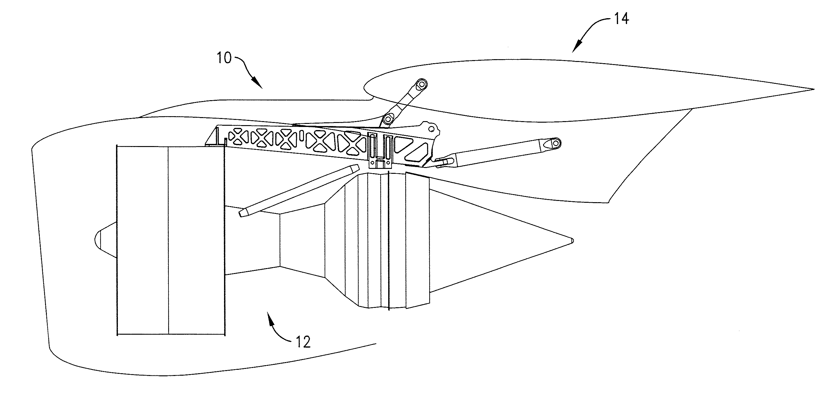
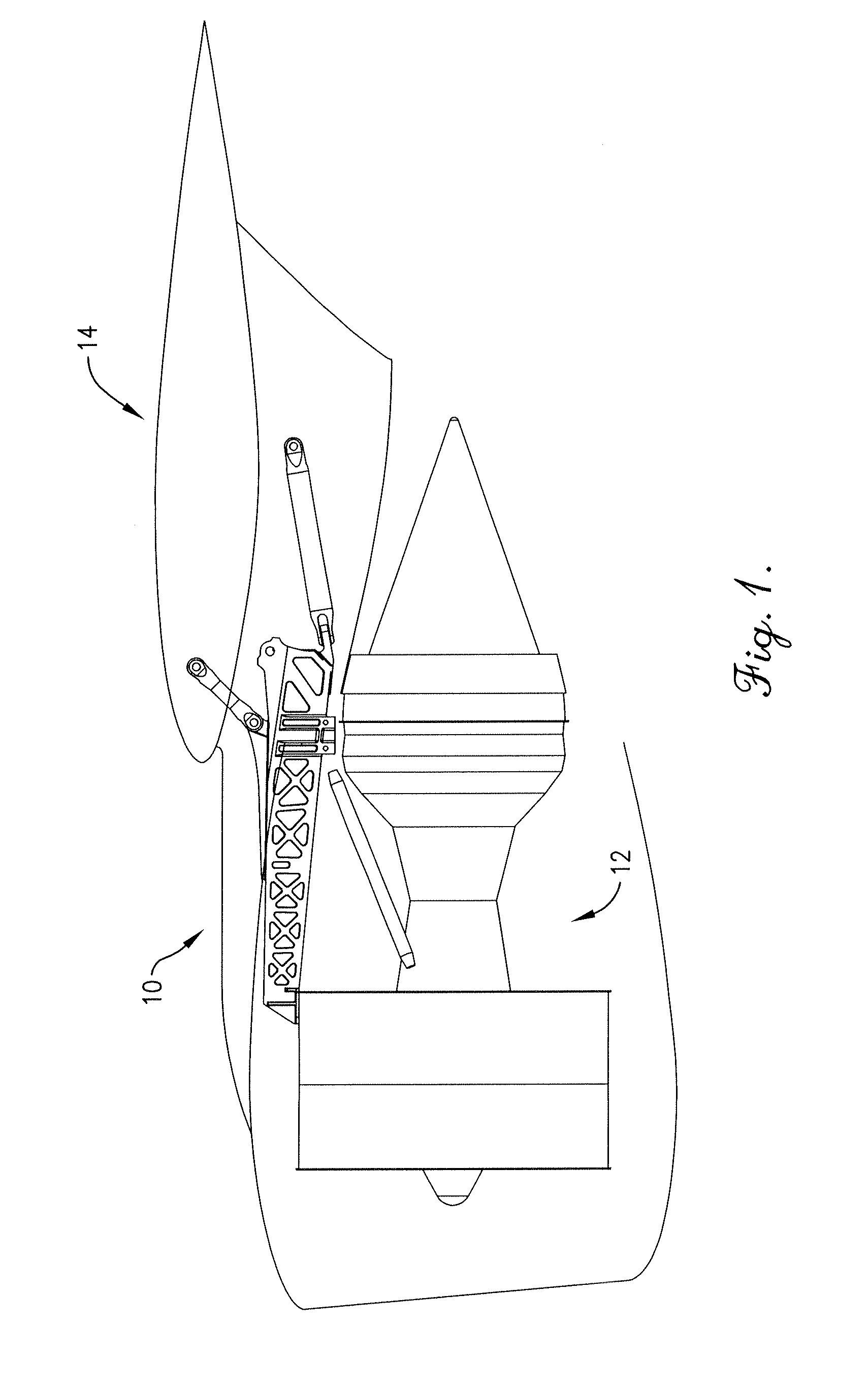
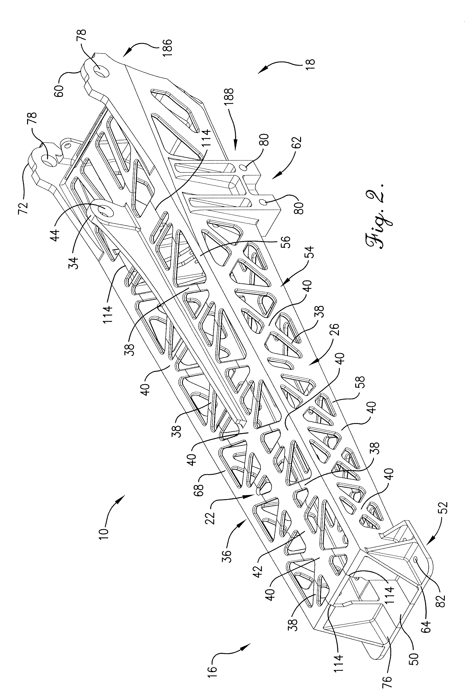
[0050]the pylon 10 is shown in FIGS. 2-4 and may be of a generally elongated box shape with a forward portion 16 and an aft portion 18 and further may have a transverse cross-sectional shape of an isosceles trapezoid or a rectangle, in some embodiments. As best shown in FIG. 4, the pylon 10 may be constructed from separately produced components 20 that broadly comprise a top wall 22, a bottom wall 24, a left side wall 26, a right side wall 28, an upper closeout fitting 30, and a lower closeout fitting 32. The pylon 10 generally requires high strength and light weight and accordingly the components 20 may be manufactured from a material such as titanium or titanium alloys like Ti-6Al-4V.
[0051]The top wall 22 generally provides mechanical strength and support for an upper wing attachment lug 34 that is coupled to the upper surface of the top wall 22. The top wall 22 may include at least a portion of an upper truss structure 36 that includes a plurality of straight, slender truss membe...
second embodiment
[0063]In a second embodiment, as shown in FIGS. 17-18, the pylon 10 may include a left forward wing attachment lug 98 and a right forward wing attachment lug 100 instead of the upper wing attachment lug 34 as described above. The left forward wing attachment lug 98 may be coupled to the left upper side rail 56, and may include an opening 102 which provides a first connection from the pylon 10 to the leading edge of the aircraft wing 14. The right forward wing attachment lug 100 may be coupled to the right upper side rail 68, and may include an opening 104 which provides a second connection from the pylon 10 to the leading edge of the aircraft wing 14. Furthermore, in various embodiments, since the upper wing attachment lug 34 is not present and support of that load is not necessary, then the top central rail 42 and the bottom central rail 48 may not be present as well.
[0064]The components 20 of the aircraft engine pylon 10—the top wall 22, the bottom wall 24, the left side wall 26, ...
third embodiment
[0076]In a third embodiment shown in FIGS. 19-21, the pylon 10 may comprise a forward truss unit 124, an aft truss unit 126, a central engine mount interface 128, a spigot fitting 130, and an aft wing attachment fitting 132.
[0077]The forward truss unit 124 generally provides support for coupling the pylon 10 to the engine 12. The forward truss unit 124 may be of a generally elongated box shape with a transverse cross-sectional shape of an isosceles trapezoid or a rectangle. The forward truss unit 124 may include a forward top wall 134, a forward bottom wall 136, a forward left side wall 138, and a forward right side wall 140. The forward top wall 134 may include a forward upper truss structure 142. The forward bottom wall 136 may include a forward lower truss structure 144. The forward left side wall 138 may include a forward left truss structure 146. The forward right side wall 140 may include a forward right truss structure 148. The forward engine attachment interface 52, as descr...
PUM
| Property | Measurement | Unit |
|---|---|---|
| Angle | aaaaa | aaaaa |
| Structure | aaaaa | aaaaa |
Abstract
Description
Claims
Application Information