Method for manufacturing a three-dimensional object
a three-dimensional object and manufacturing method technology, applied in the direction of additive manufacturing processes, electric/magnetic/electromagnetic heating, instruments, etc., can solve the problems of difficult to measure up to the present the mechanical properties of the member, for example the coefficient of elasticity, and the above method is, however, quite complex, so as to achieve simple, rapid and precise detection of special mechanical properties.
- Summary
- Abstract
- Description
- Claims
- Application Information
AI Technical Summary
Benefits of technology
Problems solved by technology
Method used
Image
Examples
first embodiment
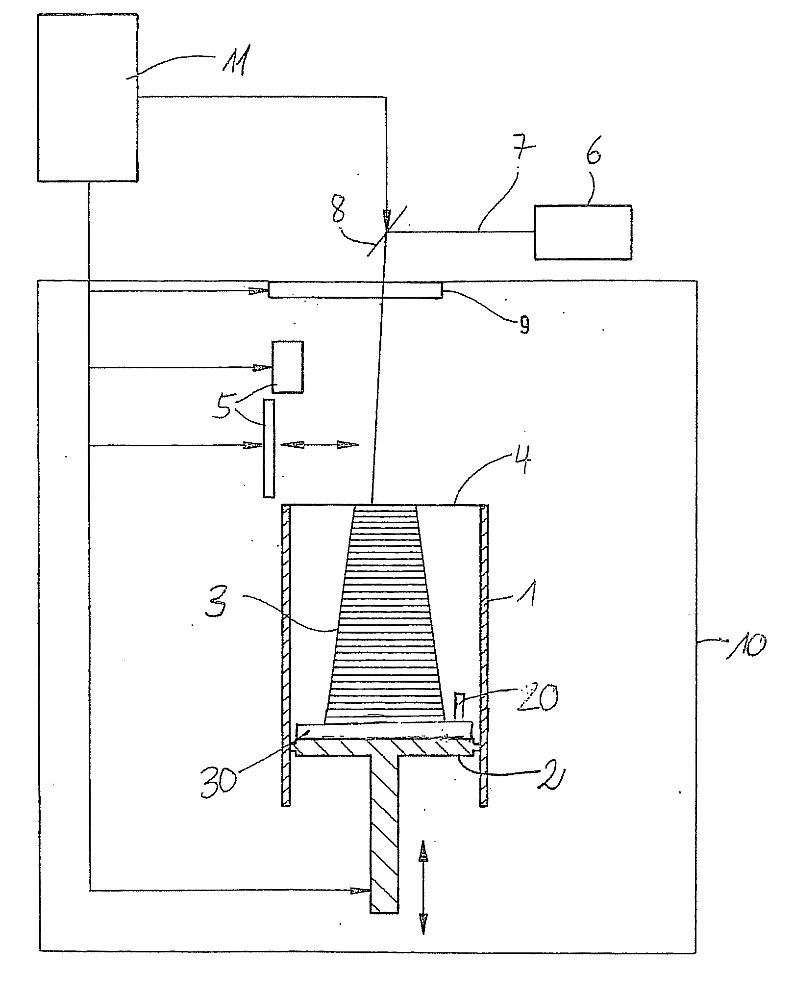
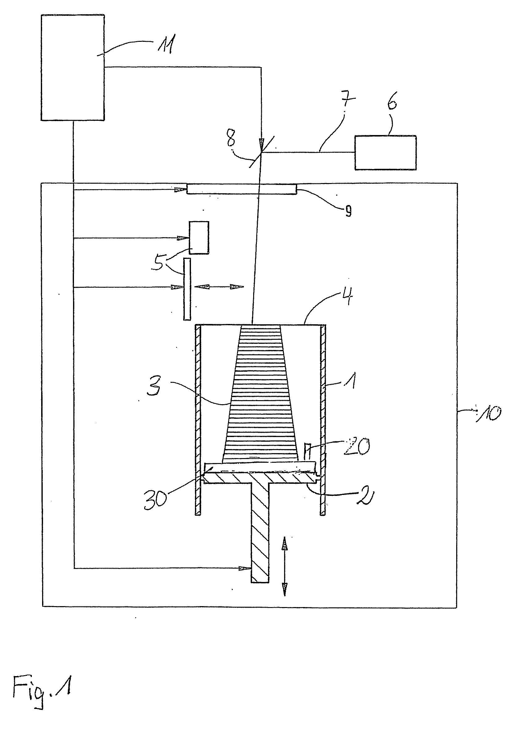
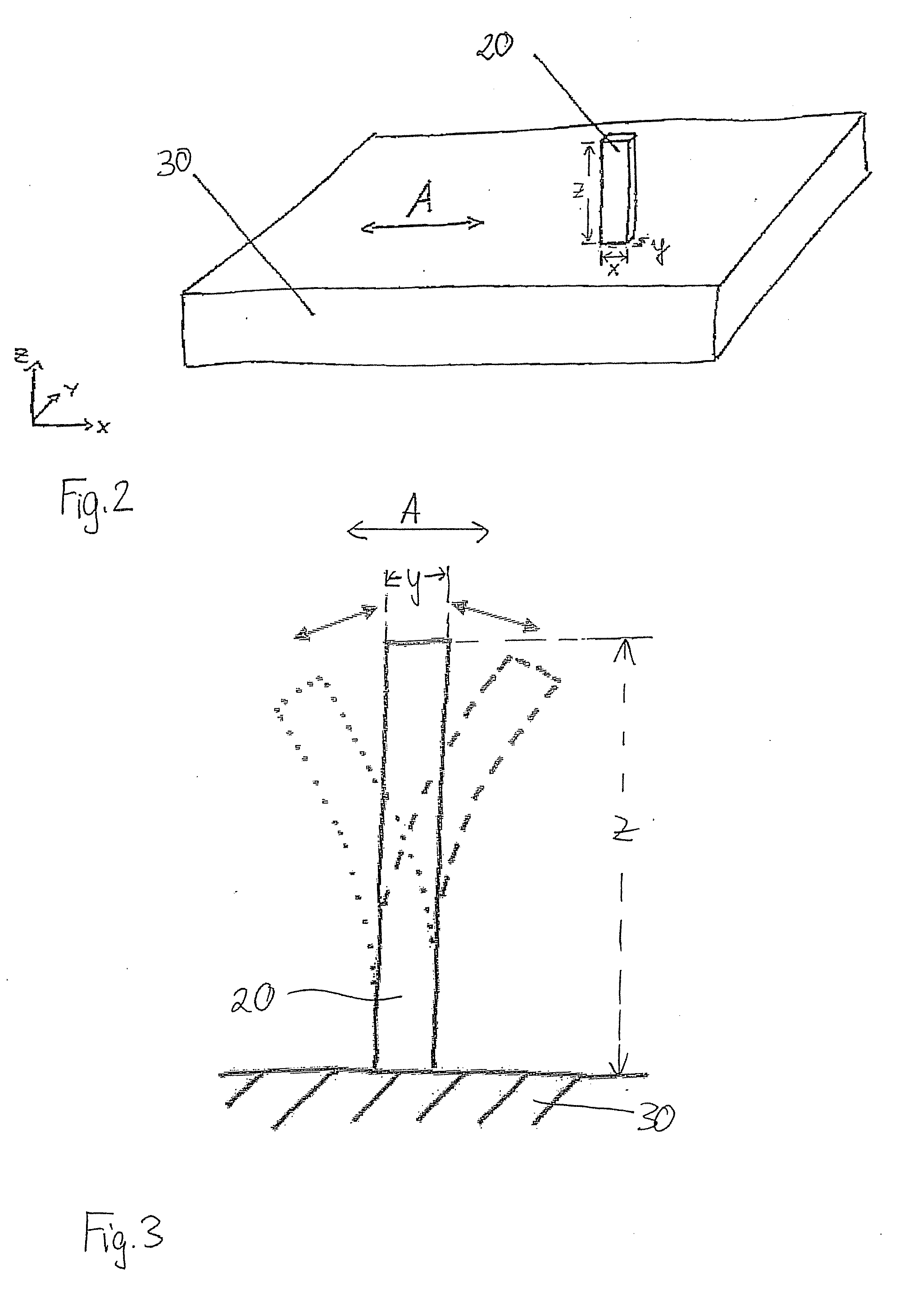
[0015]In the method according to the present invention as depicted schematically in FIG. 1, a test specimen 20 is co-built when building the object 3 to be produced itself. This test specimen 20 is excited to oscillations after the manufacture of the object 3, and then, the natural frequencies of the oscillating specimen 20 are determined. From those ones, properties of the manufactured object 3, for example the coefficient of elasticity, are determined. The CAD data which contain the geometry of the test specimen, may be contained in the same data set which also contains the object data, or the CAD data can be chosen, for example from a library, and added.
[0016]The test specimen 20 can be built anywhere at a suitable place in the building space defined by the container wall and the support. There is no need to connect it to the support 2 and / or the object 3. According to a preferred embodiment of the method, the test specimen 20 is not built freely in the building space, but on a ...
second embodiment
[0030]According to the method, the test specimen is not co-built when manufacturing the desired object, but is used for quality determination and calibration of the laser sintering device and is built separately from the object itself in a separate building process. For this purpose, one or several test specimen are built before the start of a series job, and their natural frequency spectra are analyzed and compared to the one of a reference specimen. Subsequently, the parameters of the laser sintering device are adapted accordingly, so that the objects to be produced have the desired properties. A check can be carried out by means of co-building of test specimen in the series production.
[0031]The method is not restricted to a laser sintering process. It is applicable to all layer building methods, for example to stereolithography which uses, instead of a powdery material, a liquid, light-setting resin, to three-dimensional printing according to which the powdery building material i...
PUM
| Property | Measurement | Unit |
|---|---|---|
| frequencies | aaaaa | aaaaa |
| natural frequencies | aaaaa | aaaaa |
| geometric shape | aaaaa | aaaaa |
Abstract
Description
Claims
Application Information
 - R&D
- Intellectual Property
- Life Sciences
- Materials
- Tech Scout
- Unparalleled Data Quality
- Higher Quality Content
- 60% Fewer Hallucinations
Browse by: Latest US Patents, China's latest patents, Technical Efficacy Thesaurus, Application Domain, Technology Topic, Popular Technical Reports.
© 2025 PatSnap. All rights reserved.Legal|Privacy policy|Modern Slavery Act Transparency Statement|Sitemap|About US| Contact US: help@patsnap.com


