Crawler Track Roller With Internal Spherical Spacers

a track roller and track roller technology, applied in the direction of instruments, mechanical control devices, hoisting equipment, etc., can solve the problems of metal face seal melting, roller eventual failure, and significant failure rate of crawler track rollers, and achieve the effect of cost competitive and durabl

Active Publication Date: 2011-05-26
DEERE & CO
View PDF13 Cites 38 Cited by
  • Summary
  • Abstract
  • Description
  • Claims
  • Application Information

AI Technical Summary

Benefits of technology

[0006]An object of the invention is to provide a track

Problems solved by technology

Utility crawler track rollers experience significantly high rates of failure.
One of the reasons for these failures is believed to be attributable to the internal thrust bushing experiencing non-uniform loading resulting in the bushing overheating with this heat being transferred to the adjacent metal face seal provided between an end of the rol

Method used


Image

  • Crawler Track Roller With Internal Spherical Spacers
  • Crawler Track Roller With Internal Spherical Spacers
  • Crawler Track Roller With Internal Spherical Spacers

Examples


Embodiment Construction

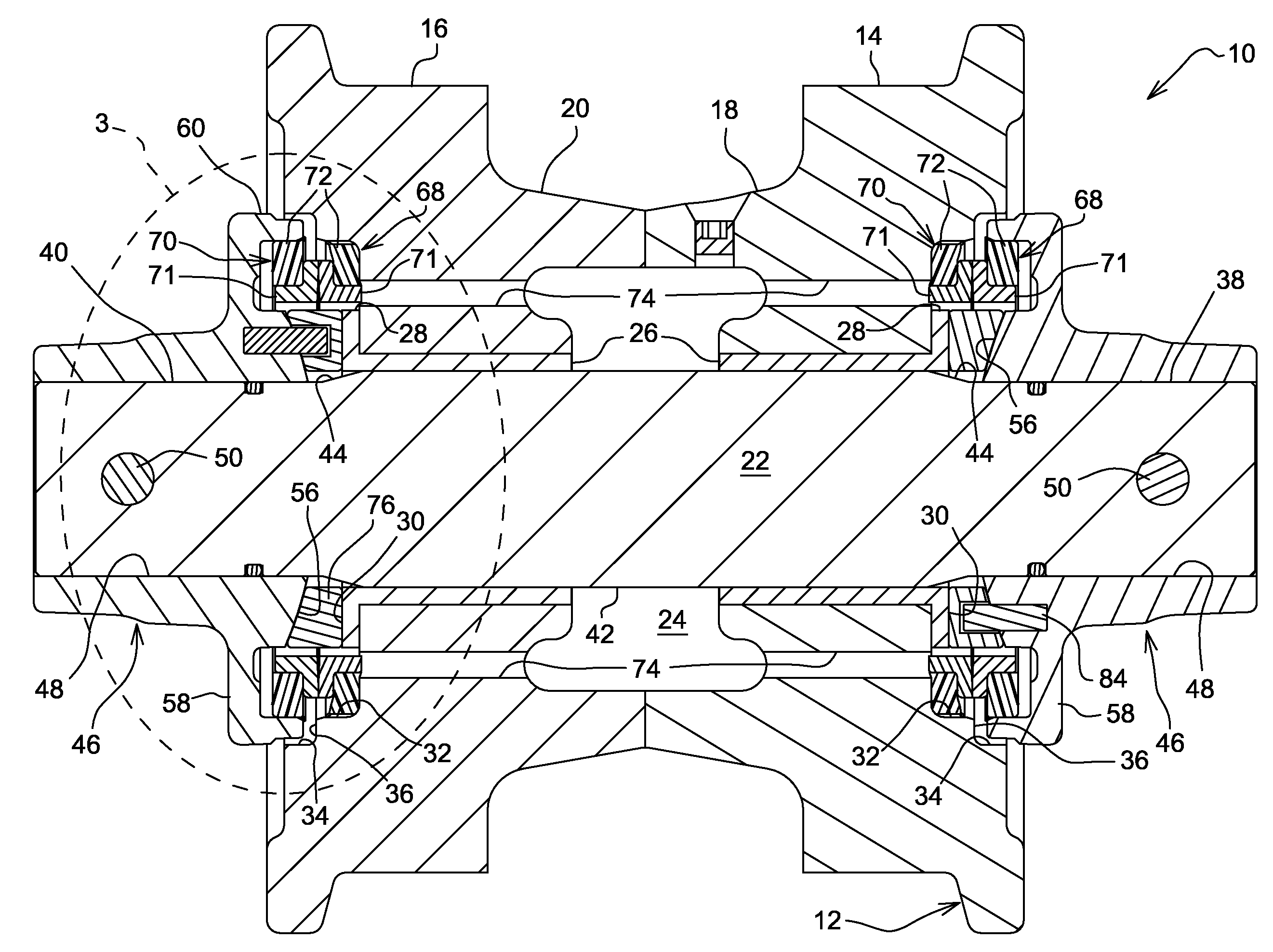
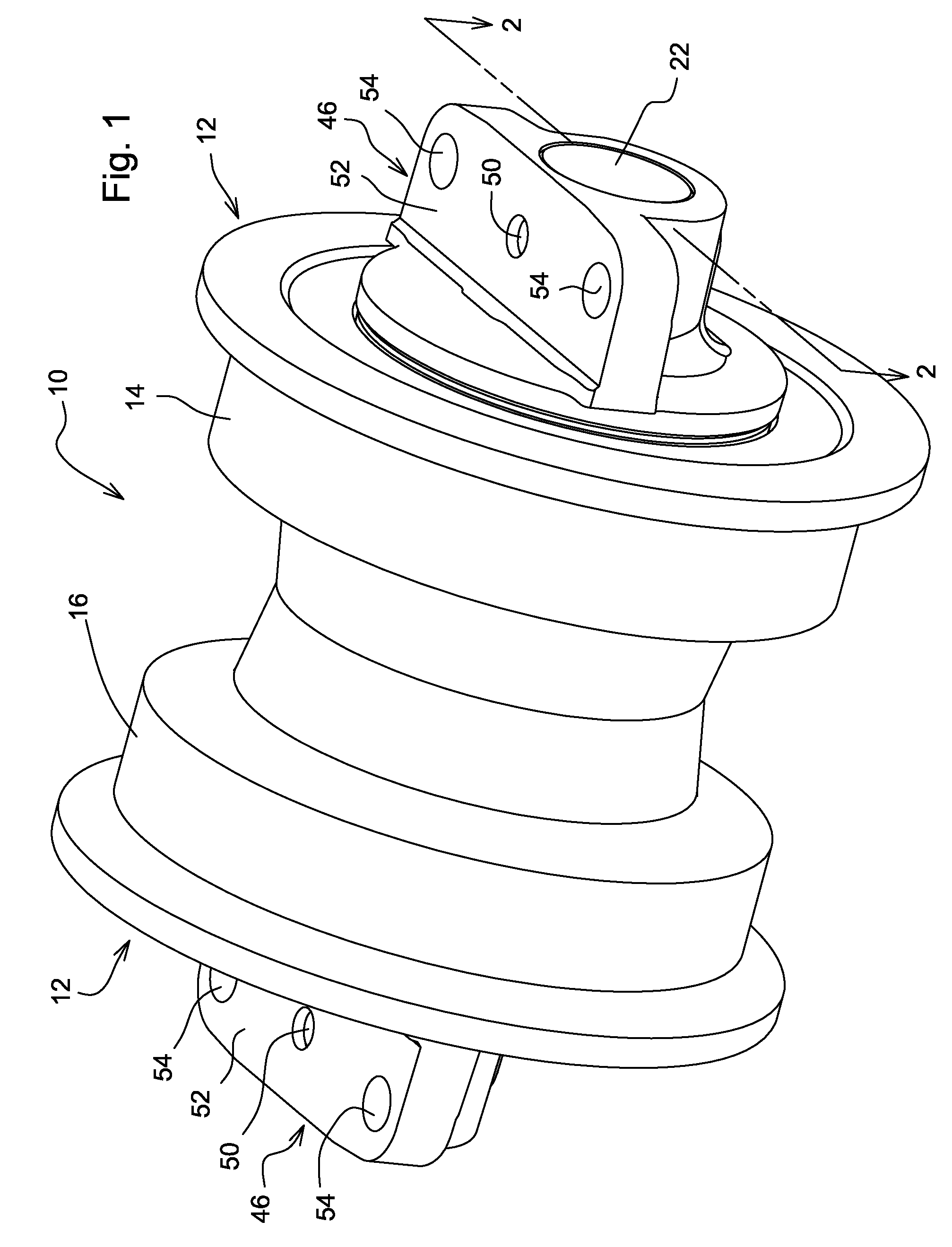
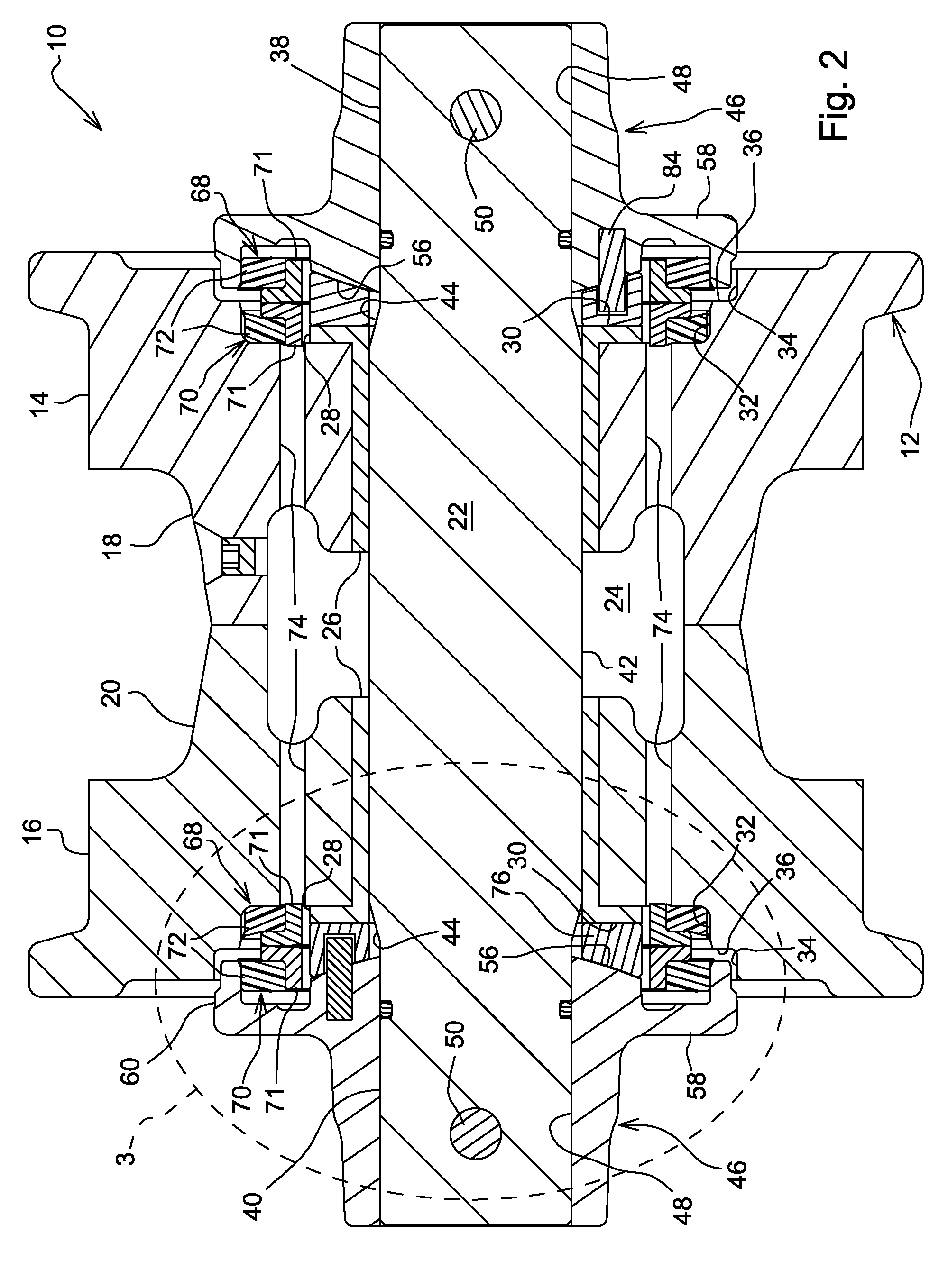
[0011]Referring now to FIGS. 1 and 2, there is shown a roller 10 of a type used together with a plurality of other rollers for supporting the endless track of a track laying tractor from the parallel support rails of a track support frame (not shown). The roller 10 includes a roller body 12 comprising right and left, mirror image halves 14 and 16, respectively, having respective confronting, inner annular flanges 18 and 20 extending axially towards each other from regions approximately halfway between inner and outer diameters of the halves 14 and 16. The annular flanges 18 and 20 have axially facing, annular abutting end surfaces, with a seam weld being formed in an exterior region of each of the flanges thereby joining the roller body halves together. The flanges cooperate with a shaft or axle 22 extending axially through the roller body 12 to form a lubricant cavity 24 which is sealed from leaking across the interface of the body 12 with the shaft by a thrust bushing assembly com...


PUM


Abstract

A roller for supporting an endless track of a track laying tractor is mounted for rotation about a shaft or axle fixed between transversely spaced, parallel rails of a track support frame. The roller is constructed of mirror image halves having axially inner ends welded together, with a pair of thrust bushings being received on the shaft and respectively disposed in supporting relationship the roller halves. Each thrust bushing includes an axially outer end defined by an annular flange having an axially outwardly facing flat bearing surface. A pair of mounting brackets are respectively received on, and fixed to opposite ends of the shaft and fixed to the pair of rails of the support frame. Non-uniform edge loading of the bushings due to minor shaft deformations due to flexure of the track support frame rails is minimized by providing axially inwardly facing ends of the brackets with spherically contoured surfaces, and by locating an annular spacer between each bracket and bushing flat bearing surface, the annular spacer having outer and inner axially facing surfaces respectively shaped complimentary to the spherical contoured surface of the bracket and the flat bearing surface of the bushing

Description

FIELD OF THE INVENTION[0001]The present invention relates to crawler track roller assemblies, and, more particularly, relates to such assemblies that include rollers received on thrust bushings located on support shafts fixed to the track frame.BACKGROUND OF THE INVENTION[0002]Utility crawler track rollers experience significantly high rates of failure. One of the reasons for these failures is believed to be attributable to the internal thrust bushing experiencing non-uniform loading resulting in the bushing overheating with this heat being transferred to the adjacent metal face seal provided between an end of the roller and a mounting bracket for the support shaft end, which, over time results in the metal face seal melting and the eventual failing of the roller.[0003]Although a more a more robust roller assembly could be used to overcome these face seal and roller failures, this would prove to be cost prohibitive in this highly cost competitive size of crawlers.[0004]Accordingly, ...

Claims


Application Information

Patent Timeline
IPC IPC(8): B62D55/15
CPCB62D55/15
Inventor MULLIGAN, PATRICK JOHN
Owner DEERE & CO
Why Eureka
Try Eureka