
Small-scale, concentrating, solar chp system

a solar energy system and small-scale technology, applied in the direction of optical radiation measurement, navigation instruments, instruments for comonautical navigation, etc., can solve the problems of affecting the accuracy of tracking, affecting the efficiency of photovoltaic collectors, etc., to achieve the effect of reducing the installation space, and reducing the cost of operation

Inactive Publication Date: 2009-08-06
RAMOT AT TEL AVIV UNIV LTD
View PDF39 Cites 31 Cited by
  • Summary
  • Abstract
  • Description
  • Claims
  • Application Information

AI Technical Summary

Benefits of technology

[0024]The object of the present invention relates to providing a high-efficiency Combined Heat and Power (CHP) solar energy system, sufficiently compact to be installed at the point of consumption, with minimal investment in infrastructure, and amenable to mass production, leading to low production cost even with a relatively small market volume, so that overall, the cost of the energy which is consumed is competitive with conventional power generation from fossil fuels.
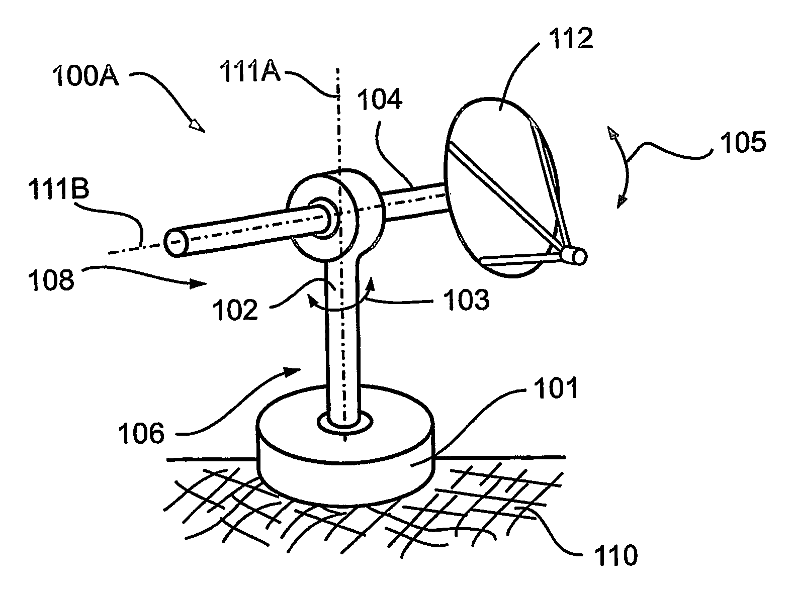
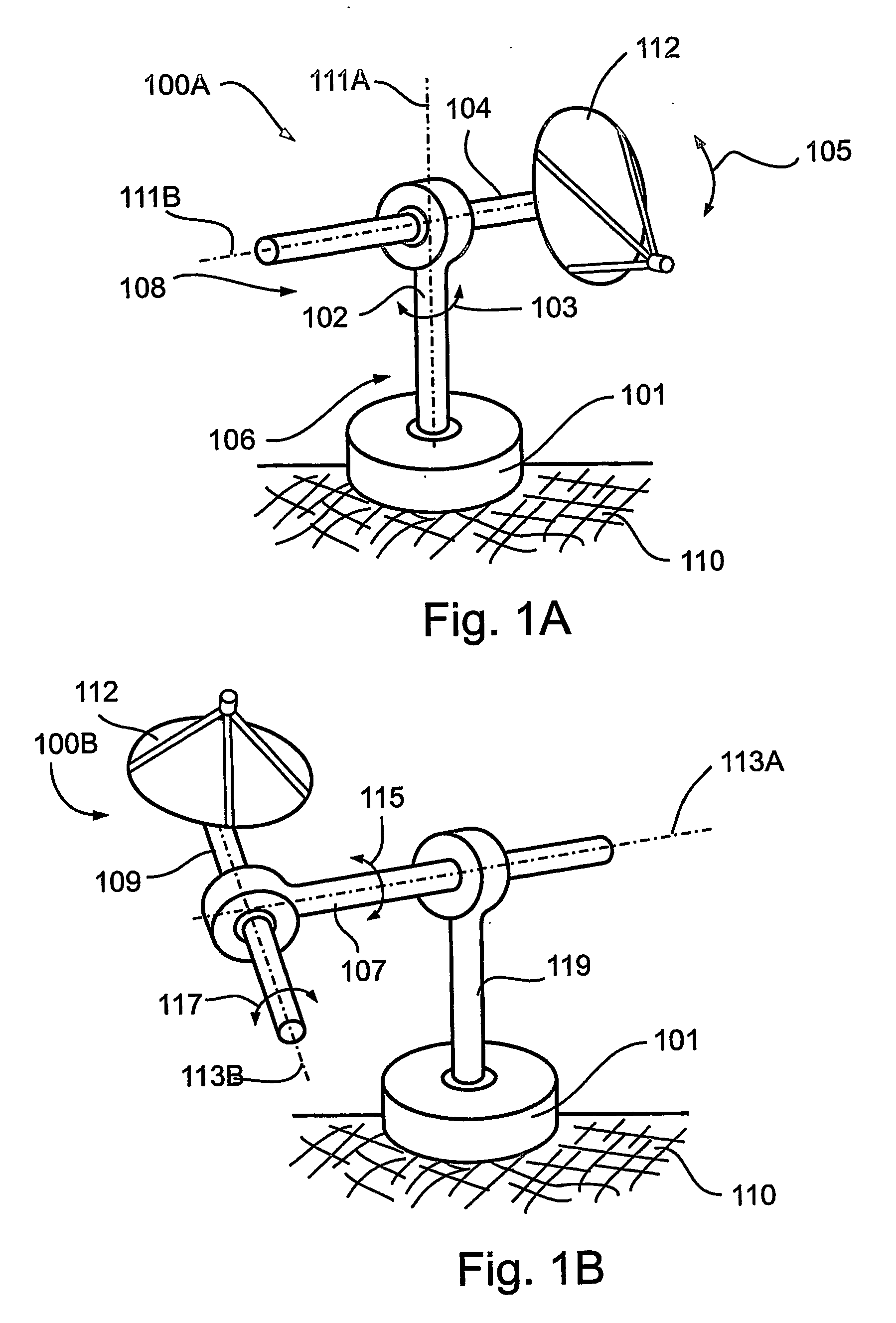
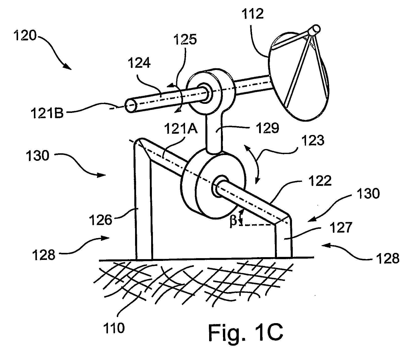
[0025]The present invention successfully addresses the shortcomings of the presently known configurations by providing a high-efficiency, small-scale, combined heat and power (CHP), concentrating solar energy system, designed specifically for residential and other relatively low-power applications, rendering it cost-effective and economically viable. Two-axis tracking of a dish-like reflector of between 1 and 2 meters in aperture ensures very high concentrating ratios of between 200 and 800 suns or even higher, if cells suitable for operation at higher concentration are available. In consequence very high coolant outlet temperatures, of 120-180° C. may be reached at the outlet of the collector coolant, which may be oil, gas, or pressurized water. The high coolant temperatures are advantageous because they may be used for air-conditioning or other applications requiring high temperatures. The higher concentration is advantageous because the efficiency of the photovoltaic cells designed for concentrated radiation is improved with higher concentration. The overall efficiency is greater than 60%. Additionally, a simple but accurate drive, designed as a radio-dial drive, with substantially zero backlash, and substantially zero drift, is provided for driving the concentrating solar energy system. Preferably, two radio-dial drives are employed and tracking is performed along two axes, of an azimuth-elevation mount, a polar mount, or a cross mount.

Problems solved by technology

As yet, power generation by these photovoltaic collectors is not economic, when compared with conventional power sources of fossil fuels.
Nonetheless, employing large concentrating solar power systems suffers from a number of drawbacks.1. Although in general, a larger system tends to be more economical than a smaller system, there are disadvantages to a larger system, as well.
Wind resistance is higher, creating high forces on the collector, and these may lead to structural deformation and may interfere with the accuracy of the tracking.
In consequence, the support structure and tracking mechanism must be massive and quite expensive.2. With an efficiency of power conversion to photovoltaic cells in the range of 10 to about 37 percent, most of the solar energy is discharged as heat.
Yet in a centralized, remote area there is little opportunity to utilize that heat, for example, in a Combined Power and Heat (CPH) system, thus the heat is wasted.3. The large concentrating solar power systems are installed away from the consumer.
Therefore additional costs due to power distribution and to transmission losses of about 10-20% of the power transmitted are incurred, raising the cost of the electric power thus produced by factors of between 2 and 3.
Yet with large concentrating systems of photovoltaic cells, transmission and distribution costs cannot be avoided since the systems are too large to be installed at the points of consumption.4. The initial investment for large concentrating solar power systems is very high, making decisions in this regard difficult, bureaucratic, and risky.5. Furthermore, competitive costs may be realized for large concentrating solar power systems if a significant number of them, equivalent for example, to at least 50 megawatt per year, is manufactured.
Yet such a market volume is difficult to guarantee; therefore, the investment and the risk associated with the development of such large systems are very high.6. Large concentrating solar power systems must be installed by trained personnel with specialized equipment and facilities, requiring special contractors, and special licenses, which increase their costs.7. Large concentrating solar power systems would generally require environmental studies and permits, so as to further increase their costs.8. Centralized power plants in general are vulnerable to malfunction and sabotage.
A single incident of this nature can disrupt power supply for a very large segment of the population.
Yet, the system of Komp relies on linear concentrators, does not use tracking, and achieves a concentration ratio of only about 2.1 to 1.
However, the system of O'Neill, et al. is relatively large, producing 120 kilowatt peak thermal output and using 245 square meters of sun-tracking collector aperture area; therefore, it is not applicable to domestic and other small-scale or rooftop applications.

Method used


Image

  • Small-scale, concentrating, solar chp system
  • Small-scale, concentrating, solar chp system
  • Small-scale, concentrating, solar chp system

Examples


first embodiment

[0112]In accordance with a first embodiment, T1 may be between 90 and 120° C. and T2 may be between 60 and 80° C.

second embodiment

[0113]In accordance with a second embodiment, T1 may be between 120 and 180° C. and T2 may be between 80 and 120° C.

[0114]Referring further to the drawings, FIG. 7 schematically illustrates a single-solar-collector CHP circuit 170, in accordance with the present invention.

[0115]Solar concentrator unit 10 of circuit 170 includes two interfaces: an interface 172, for electrical connections, and an interface 174, for coolant connections. Preferably, electrical interface 172 connects to an inverter 176, which converts the DC electricity produced by power conversion unit 34 (FIGS. 4A-4B, and 5) to AC power and adjusts the frequency and phase to match that of the grid. The electric power from inverter 176 is connected to a main electrical box 182 and provides electrical power 186 to residential unit 180.

[0116]Preferably, residential unit 180 is also connected to a grid 184. When power generation is insufficient, backup power may be supplied by grid 184. Alternatively, when power generatio...


PUM


Abstract

A high-efficiency, small-scale, combined heat and power, concentrating solar energy system (200), designed specifically for residential and other relatively low-power applications, rendering it cost-effective and economically viable. Two-axis tracking of a dish-like reflector (10) of between 1 and 2 meters in aperture ensures very high concentrating ratios of between 200 and 8-suns or even higher. In consequence very high coolant outlet temperatures, of 120-180° C. may be reached at the outlet of the collector coolant, which may be oil, gas, or pressurized water. The high coolant temperatures are advantageous because they may be used for air-conditioning. The high concentration is advantageous because the efficiency of the photo_voltaic cells is improved with higher concentration. The overall efficiency is greater than 60%. Additionally, a simple but accurate drive, designed as a radio-dial drive (14), with substantially zero backlash, and substantially zero drive, is provided for driving the concentrating solar energy system. Preferably, two radio-dial drives are employed and tracking is performed along two axes, of an azimuth-elevation mount, a polar mount, or a cross mount.

Description

FIELD AND BACKGROUND OF THE INVENTION[0001]The present invention relates to high-efficiency, small-scale, combined heat and power (CHP), concentrating solar energy systems, and to a radio-dial drive, for celestial tracking mechanisms, which may be used with the concentrating solar energy systems.[0002]Solar photovoltaic collectors are usually of the flat plate type, consisting of a large area of stationary photovoltaic cells that receive natural sunlight, but do not follow the apparent motion of the sun. As yet, power generation by these photovoltaic collectors is not economic, when compared with conventional power sources of fossil fuels.[0003]One approach to reducing the cost of power generation by solar photovoltaic collectors is to concentrate the sunlight by optical means, such as lenses and (or) mirrors, thus reducing the actual area of the photovoltaic cells, per kW. Current cells can be activated by solar radiation, which is concentrated by a factor of up to 1,000; therefore...

Claims


Application Information

Patent Timeline
Patent Type & Authority Applications(United States)
IPC IPC(8): H01L31/058F24J2/38F24JF24J2/54F24S23/71F24S50/20F24V30/00H01L31/052
CPCF24J2/12F24J2/542F24J2/5424H01L31/0522Y02E10/60Y02E10/42Y02E10/47Y02E10/52H01L31/058H02S40/44H01L31/0547F24S30/455F24S23/71F24S30/452H01L31/054Y02E10/40
Inventor KRIBUS, ABRAHAMLEVY, NATHAN-ARIEKAFTORI, DANIEL
Owner RAMOT AT TEL AVIV UNIV LTD
Learn More