Digital holographic microscope

a holographic microscope and microscope technology, applied in the field of digital holographic microscopes, can solve the problems of preventing good acquisition of images, difficult interpretation of images, and affecting the quality of images, and achieves the effects of reducing time delay, facilitating high-quality three-dimensional images, and reducing costs

Inactive Publication Date: 2006-06-22
UNIV LIBRE DE BRUXELIES
View PDF8 Cites 30 Cited by
  • Summary
  • Abstract
  • Description
  • Claims
  • Application Information

AI Technical Summary

Benefits of technology

[0014] In particular, certain embodiments provide a method and an instrument for obtaining three-dimensional images of the specimen and of the fluorescence field of this specimen, that is to say for obtaining information about the distribution of the fluorescence over the entire volume of the specimen, and optionally to monitor their change over time, and to do so with a minimum time delay between each image acquisition.
[0015] Certain embodiments provide a method and a device that do not require excessive complex manipulation and which cost is thus competitive, especially compared with confocal microscopy.
[0016] Certain embodiments provide a microscope for obtaining easily high quality three-dimensional images of a specimen, and namely with minimal optical adjustments.

Problems solved by technology

However, one of the problems encountered in conventional fluorescence microscopy is that of the fluorescence emitted by elements lying outside the plane of sharpness.
This parasitic light prevents good acquisition of the image by adding substantial background noise.
The images become very difficult to interpret when thick biological specimens, such as embryons, are observed.
However, confocal microscopy also has its own drawbacks.
One drawback of confocal microscopy is that this technique requires complete scanning of the specimen by an optomechanical device.
This operation requires a relatively long time (typically of the order of a few seconds) to analyze a volume before the image is available to be displayed.
Furthermore, the exciting source used in confocal microscopy is generally an argon or argon-krypton laser that may damage biological specimens.
Another drawback is that the exciting sources do not allow the entire wavelength range needed for observation in fluorescence to be easily covered.
Finally, confocal microscopy is an extremely sophisticated technique that requires great precision during manipulation and is also expensive.

Method used


Image

  • Digital holographic microscope
  • Digital holographic microscope
  • Digital holographic microscope

Examples


Embodiment Construction

Light Sources Used for the Digital Holography

[0095] Different types of sources can be used for illuminating the sample to be studied.

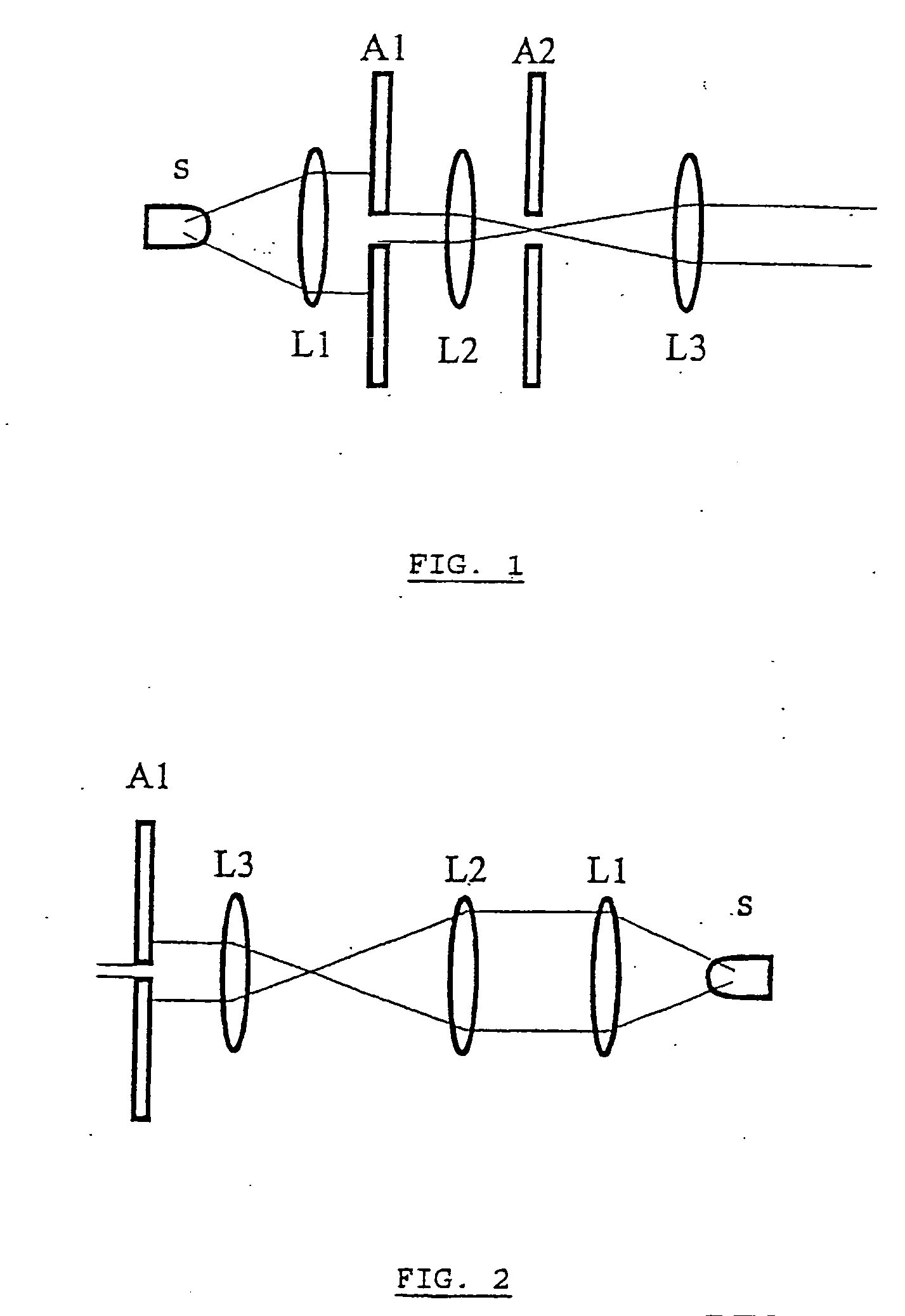
[0096] A first type of light source that can be used in the instrument corresponds to a partially spatially coherent source as shown in FIG. 1. An achromatic lens L1 collimates the light rays emitted by an extended spatially incoherent wavelength-filtered source S, for example an LED (light-emitting diode), to a first iris diaphragm A1 of adjustable aperture. The aperture A1 limits the angular spectrum of the source so as to increase the spatial coherence of the light. A second achromatic lens L2 creates a secondary source in its focal plane in which a second iris diaphragm A2 limits the size of the source. A third lens L3 forms a collimated beam. For digital holography, the focal lengths of L1, L2, L3 are, for example, 100 mm.

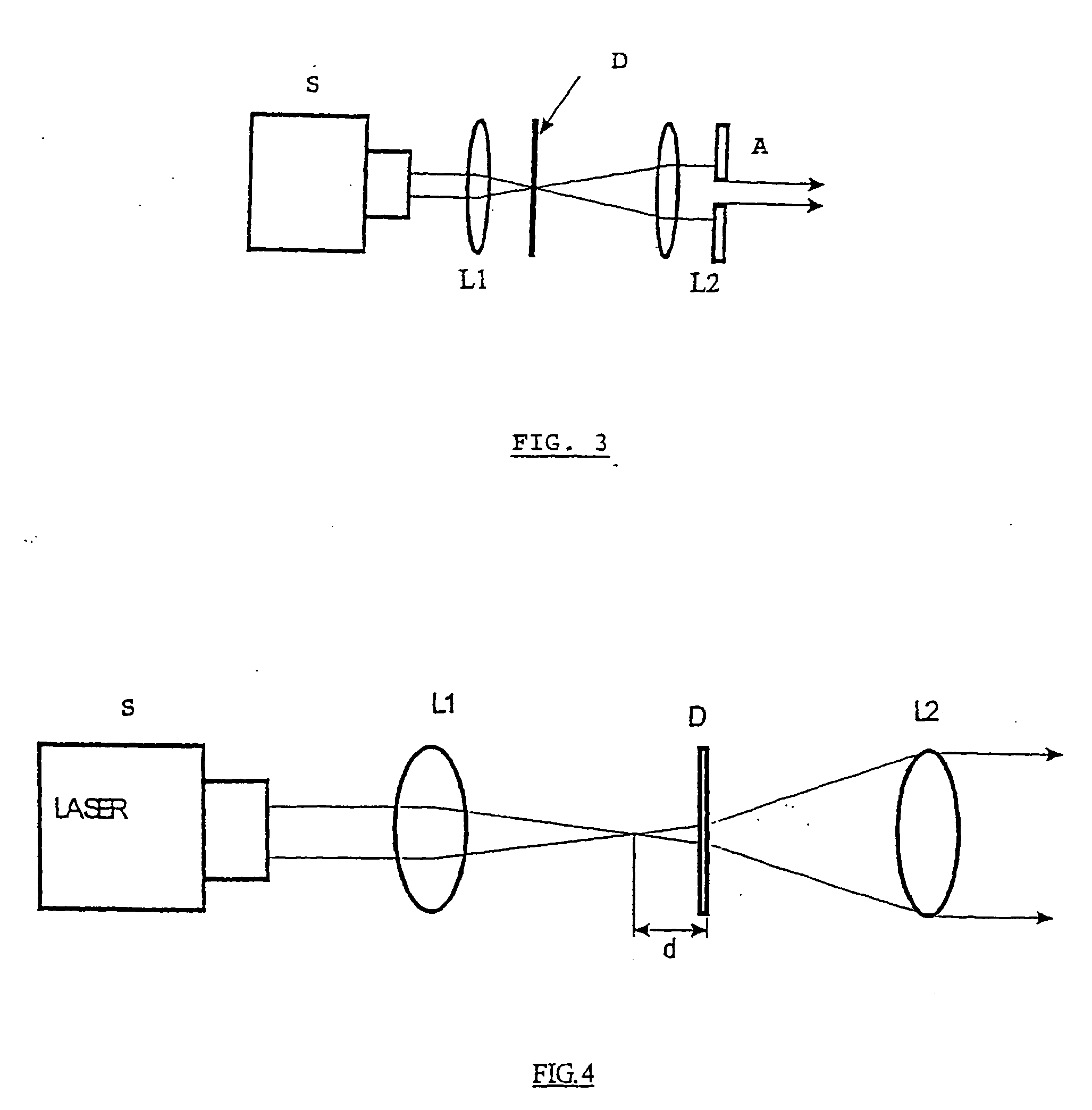
[0097] A second type of light source that can be used in the instrument corresponds to a partially coherent source as shown...


PUM

PropertyMeasurementUnit
focal lengthsaaaaaaaaaa
digital holographic microscopeaaaaaaaaaa
spectral widthaaaaaaaaaa

Abstract

A method and device for obtaining a sample with three-dimensional microscopy, in particular a thick biological sample and the fluorescence field emitted by the sample. One embodiment includes obtaining interferometric signals of a specimen, obtaining fluorescence signals emanating from the specimen, recording these signals, and processing these signals so as to reconstruct three-dimensional images of the specimen and of the field of fluorescence emitted by the specimen at a given time. Another embodiment includes a digital holography microscope, a fluorescence excitation source illuminating a specimen, where the microscope and the fluorescence excitation source cooperate to obtain interferometric signals of the specimen and obtain fluorescence signals emanating from the specimen, means for recording the interferometric signals and fluorescence signals, and means for processing the interferometric signals and the fluorescence signals so as to reconstruct three-dimensional images of the specimen and of the field of fluorescence emitted by the specimen at a given time.

Description

RELATED APPLICATIONS [0001] This application is a continuation in part of U.S. application Ser. No. 10 / 742,054 filed on Dec. 18, 2003, which is hereby incorporated by reference.FIELD OF THE INVENTION [0002] The present invention relates to a method and to an instrument for obtaining three-dimensional images of a specimen or sample by microscopy and for obtaining, in three dimensions, the field of fluorescence emitted by this specimen, said specimen being either fluorescent or prelabeled using one or more fluorochromes. [0003] The present invention also relates to a particular microscope for obtaining three-dimensional images of a specimen. [0004] One of the applications of said method and of said instrument relates more particularly to obtaining three-dimensional images of the fluorescence emitted by biological specimens, that may be thick, for the purpose of observing their dynamic behavior and their change over time. PRIOR ART [0005] Conventional fluorescence microscopy has provid...

Claims


Application Information

Patent Timeline
Patent Type & Authority Applications(United States)
IPC IPC(8): G01B11/02G01N21/64G02B21/06G02B21/22G03H1/08
CPCG01N21/6458G02B21/16G02B21/365G03H1/0005G03H1/0866G03H1/041G03H2001/0456G03H2001/0458G03H2222/24G03H2223/26G03H2001/005G03H1/0443G03H1/0465G03H2001/0452G03H2223/14
Inventor DUBOIS, FRANCKYOURASSOWSKY, CATHERINE
Owner UNIV LIBRE DE BRUXELIES
Why Eureka
Try Eureka