Backlight unit and display device using same

a backlight unit and display device technology, applied in lighting and heating apparatus, planar/plate-like light guides, instruments, etc., can solve the problems of difficult to reduce the cost involved in the assembling process, difficult to reduce the cost involved in the manufacturing of parts, and difficult to reduce the overall shape, so as to simplify the assembling process and achieve high brightness. , the effect of high brightness

Inactive Publication Date: 2011-05-26
PANASONIC INDAL DEVICES SUNX
View PDF2 Cites 7 Cited by
  • Summary
  • Abstract
  • Description
  • Claims
  • Application Information

AI Technical Summary

Benefits of technology

[0021]With this configuration, the light emitted from the light source in other directions than the light incident surface is reflected toward the light incident surface by the surrounding member or the surrounding portion. This makes it possible to realize high brightness.
[0022]The substrate may include a substrate reflection layer provided around the light source. Therefore, the light emitted toward the substrate is reflected by the substrate reflection layer to go toward the light incident surface. This makes it possible to realize high brightness.
[0023]The light source may be kept in close contact with the light incident surface. Thus, the light emitted from the light source goes toward the light incident surface with no waste.
[0024]The light source may be oriented so that the optical axis thereof extends in the direction parallel to the plane of the substrate. This eliminates the need to specially redesign the light guide plate, which makes it possible to employ a conventional light guide plate.
[0025]In accordance with another aspect of the present invention, there is provided a display device including the backlight unit mentioned above. Therefore, it is possible to simplify the assembling process and to reduce the number of parts as compared with the prior art. In case where the display device is employed in, e.g., a PLC, it is possible to reduce the size of the display device as compared with the prior art.
[0026]With the backlight unit of the present invention and the display device using the same, it is possible to reduce the manufacturing cost while realizing improved assembling convenience and increased space saving.

Problems solved by technology

This poses a problem in that the assembling process becomes cumbersome, thereby making it difficult to reduce the cost involved in the assembling process.
This makes it hard to reduce the cost involved in manufacturing the parts.
This makes it hard to reduce the overall shape.

Method used


Image

  • Backlight unit and display device using same
  • Backlight unit and display device using same
  • Backlight unit and display device using same

Examples


first embodiment

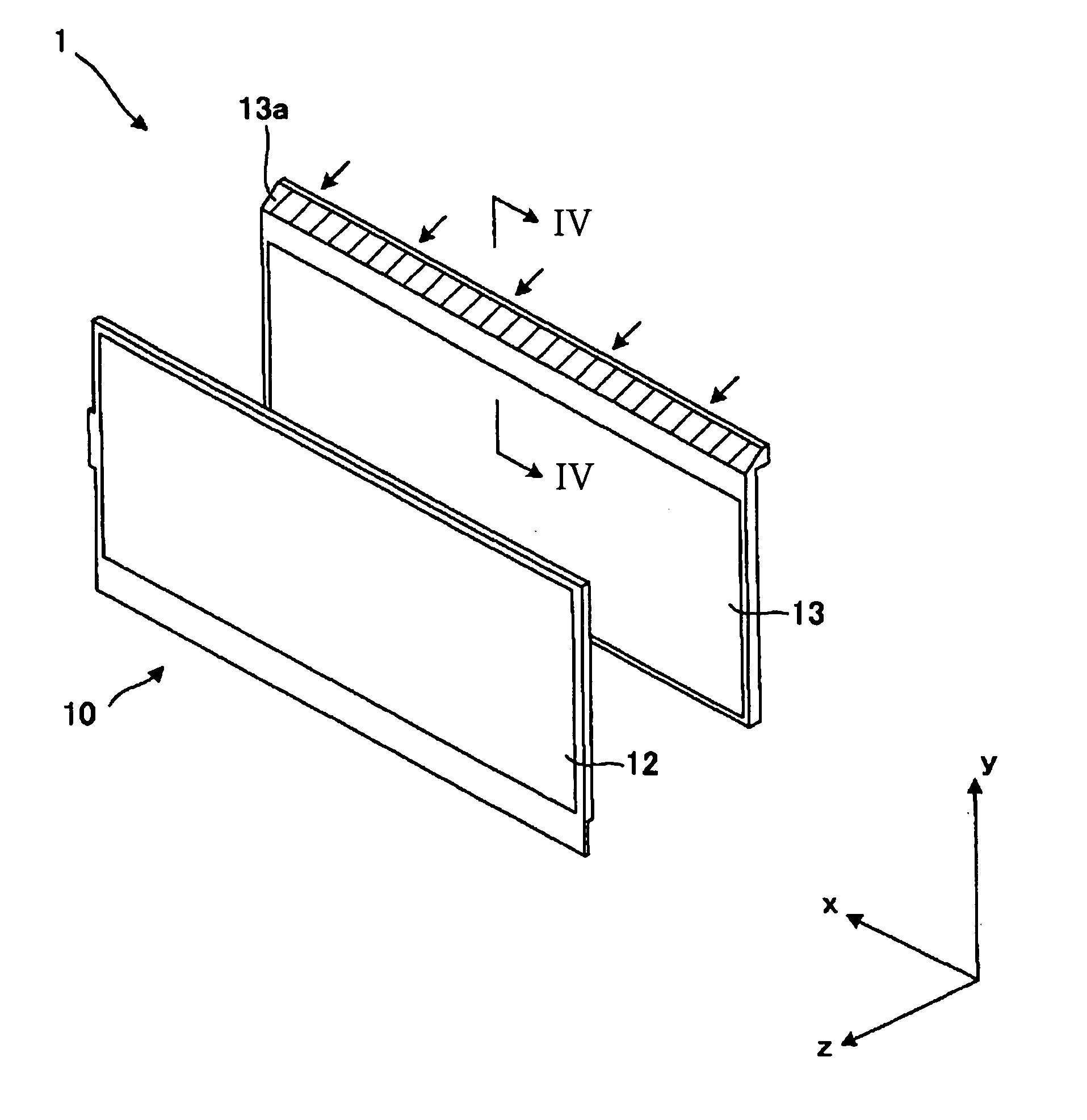
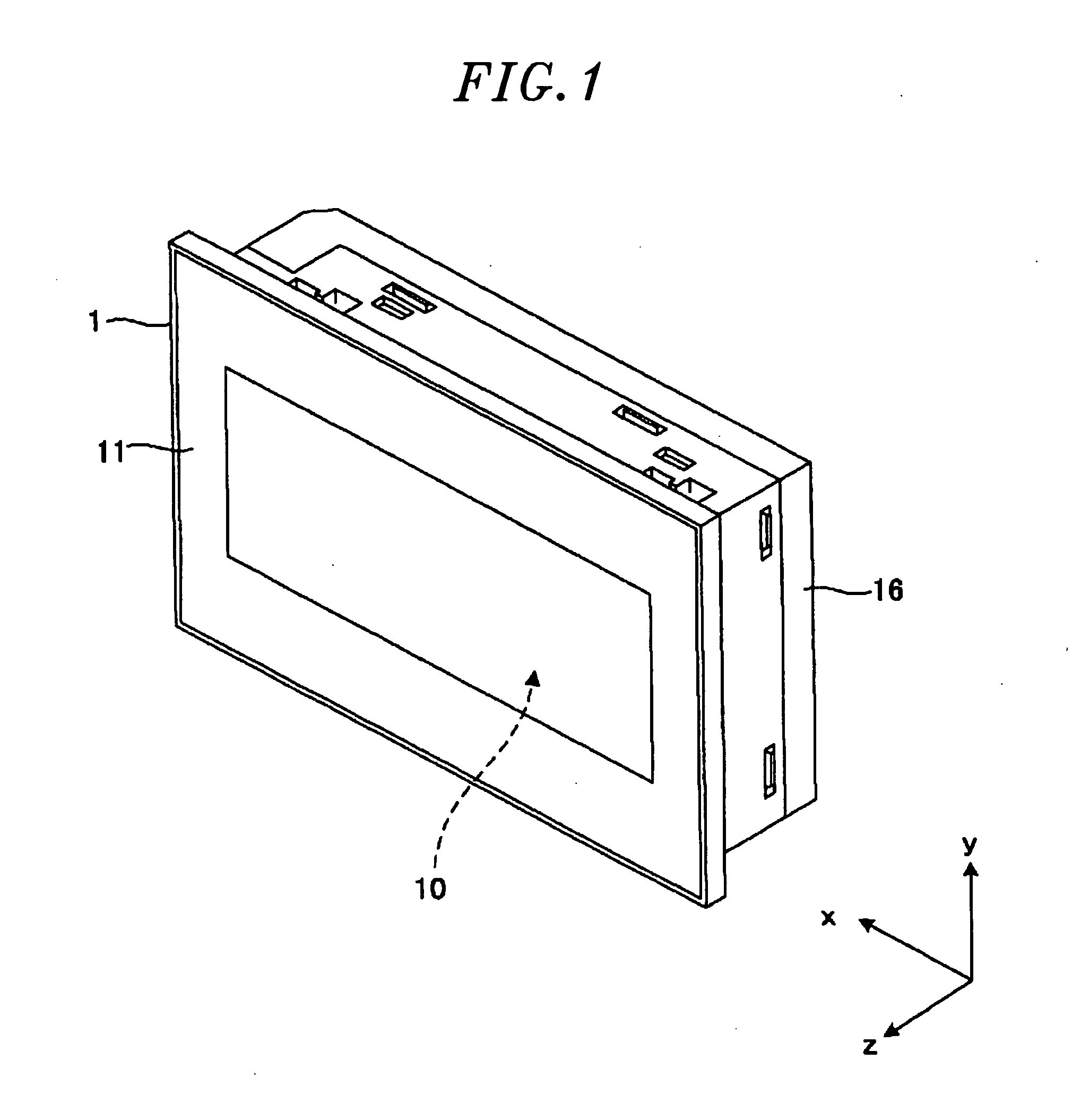
[0046]FIG. 1 is a perspective view showing the overall structure of a display device 1 according to a first embodiment of the present invention. In the following description, the longitudinal direction extending along the plane of the display device 1 in FIG. 1 will be referred to as “x-direction”, the direction parallel to the plane of the display device 1 and orthogonal to the x-direction as “y-direction”, and the direction orthogonal to both the x-direction and the y-direction and extending in the thickness direction of the display device 1 as “z-direction”. In the display device 1 of the first embodiment shown in FIG. 1, the positive side in the z-direction will be called “front”.

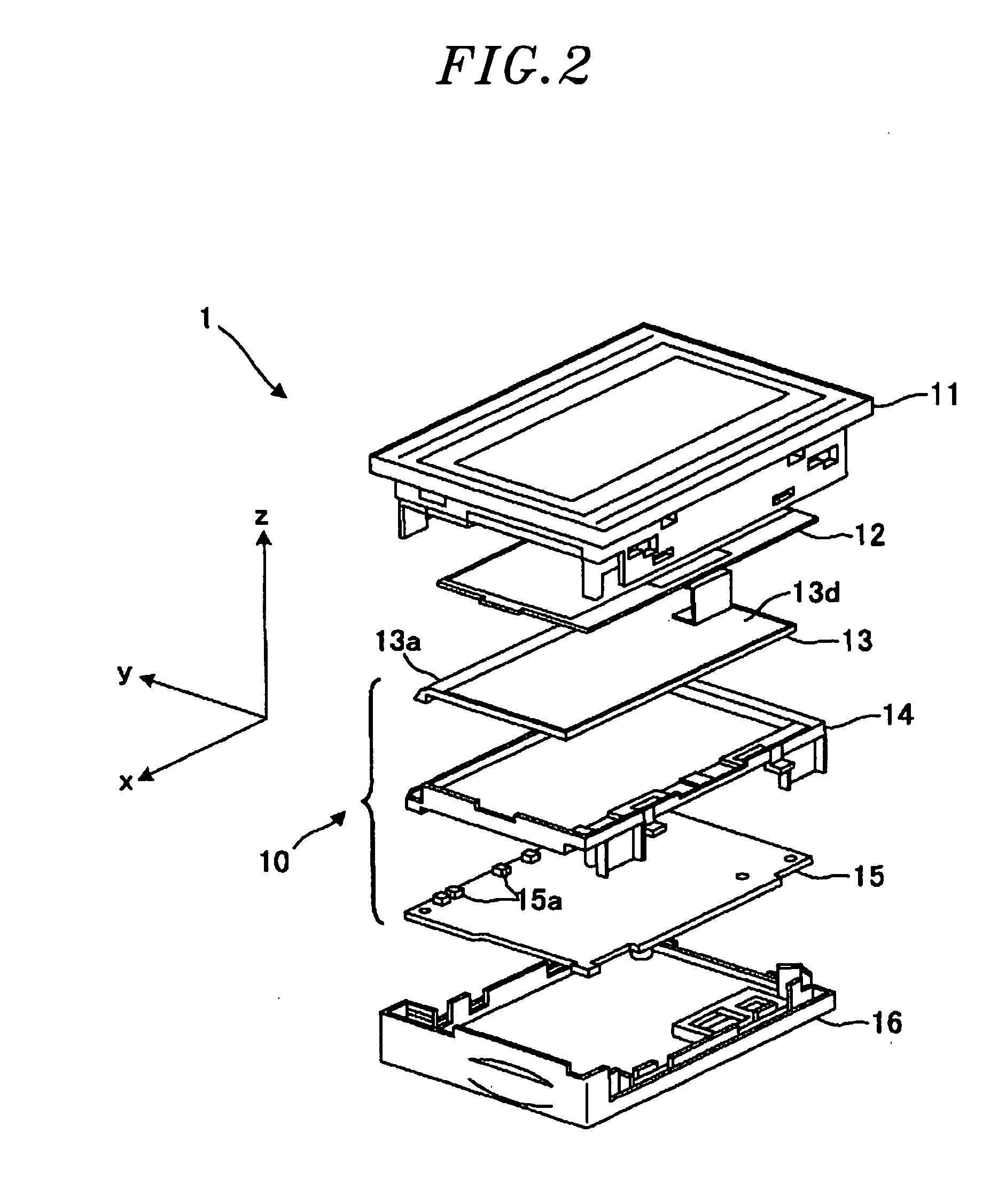
[0047]The display device 1 of the first embodiment as exploded will be described with reference to FIG. 2, which is an exploded perspective view showing the structure of a backlight unit 10 employed in the display device 1 of the first embodiment. As shown in FIG. 1, the display device 1 is formed into ...


PUM


Abstract

A backlight unit arranged at the rear side of a liquid crystal panel for illuminating the liquid crystal panel. The backlight unit includes a light source for emitting light and a light guide plate. The light guide plate includes a light incident surface on which the light emitted from the light source is incident, a main reflection surface for internally reflecting the light incident on the light incident surface and a light launching surface from which the light reflected by the main reflection surface is launched toward the liquid crystal panel. The backlight unit further includes a frame for supporting the light guide plate and a substrate arranged at the opposite side of the frame from the liquid crystal panel and mounted with electronic parts. The light source is mounted to the substrate.

Description

FIELD OF THE INVENTION[0001]The present invention relates to a backlight unit for irradiating light from a light source on the rear surface of a liquid crystal panel through a light guide plate, and a display device using the same.BACKGROUND OF THE INVENTION[0002]A conventional display device 100 shown in FIG. 17 is used as a display device in, e.g., a programmable logic controller (PLC) for controlling a production line or the like. The display device 100 is formed into a substantially box-like shape by means of a front housing part 101 and a rear housing part 107. Accommodated within the display device 100 are a liquid crystal panel 102, a light guide plate 103, a frame 104, a circuit board 105 and a support substrate 106. The light guide plate 103 has a flat shape with a specified thickness and is supported by the frame 104. Integrated circuits for performing communication or arithmetic processing or other electronic parts are mounted on the circuit board 105. The circuit board 1...

Claims


Application Information

Patent Timeline
Patent Type & Authority Applications(United States)
IPC IPC(8): F21V7/22
CPCG02B6/0018G02B6/0086G02B6/0073G02B6/0055
Inventor OSUMI, SACHIUEMATU, EIITIDOI, KENJIKATSUYA, HIROKI
Owner PANASONIC INDAL DEVICES SUNX
Why Eureka
Try Eureka