Image forming apparatus

a technology of image forming apparatus and forming tube, which is applied in the direction of electrographic process apparatus, instruments, optics, etc., can solve the problems of reducing productivity and increasing the amount of residual toner, and achieve the effects of suppressing a lowering productivity, stabilizing a density of images, and suppressing an increase in toner consumption

Inactive Publication Date: 2011-05-26
CANON KK
View PDF3 Cites 26 Cited by
  • Summary
  • Abstract
  • Description
  • Claims
  • Application Information

AI Technical Summary

Benefits of technology

[0006]A principal object of the present invention is to provide an image forming apparatus, in which an image is formed with color toners and a transparent toner, capabl

Problems solved by technology

However, when the transparent toner patch is formed with the same frequency as that for the color toner patches in the image forming appara

Method used


Image

  • Image forming apparatus
  • Image forming apparatus
  • Image forming apparatus

Examples


embodiment 1

1. General Structure and Operation of Image Forming Apparatus

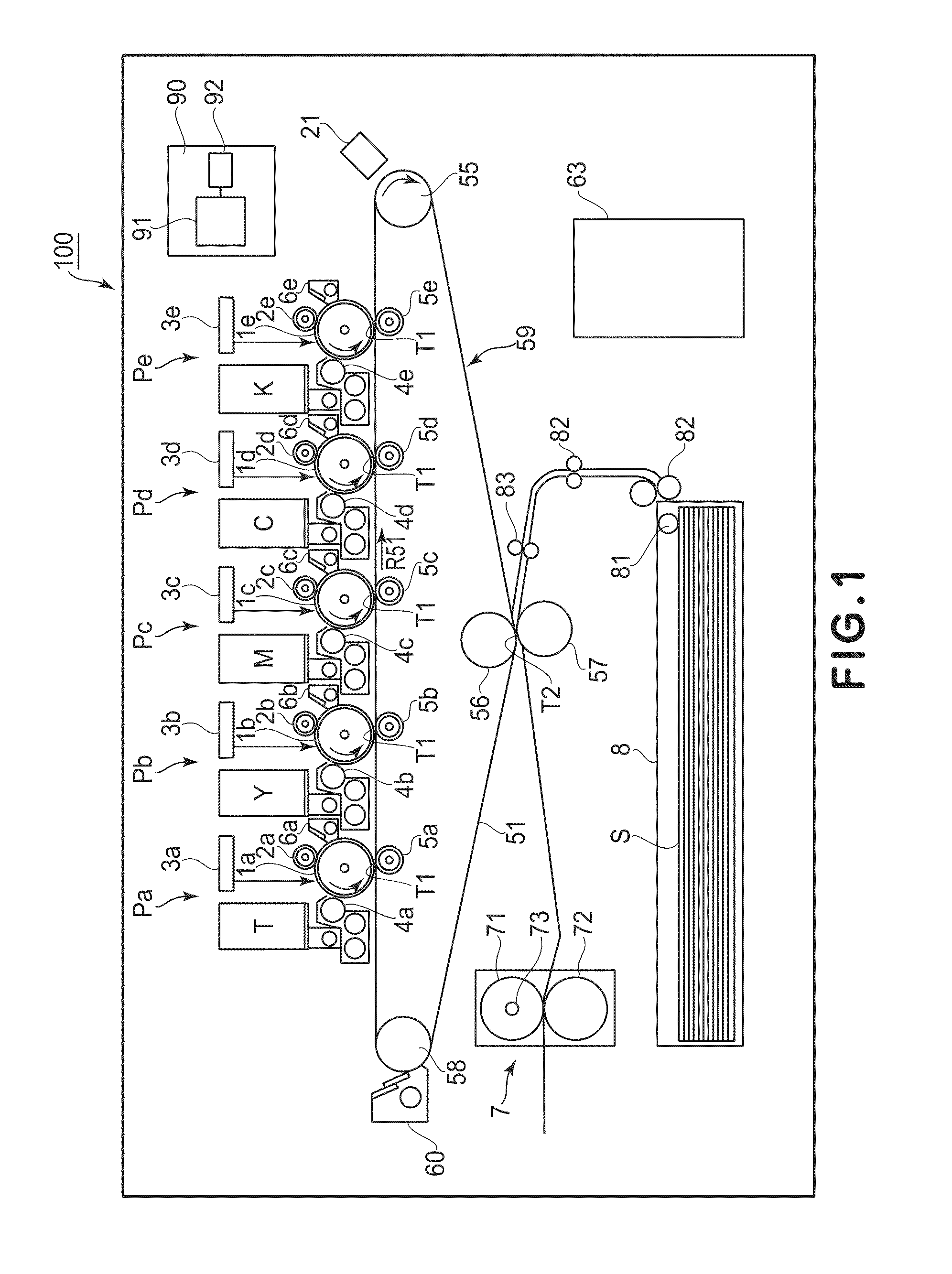
[0030]FIG. 1 is a schematic sectional view for illustrating a structure of an image forming apparatus 100 in this embodiment. The image forming apparatus 100 is an electrophotographic color image forming apparatus including an intermediary transfer belt 51 as an intermediary transfer member. A main assembly of the image forming apparatus 100 includes first to fifth image forming portions Pa, Pb, Pc, Pd and Pe for five colors as image forming means. The first to fifth image forming portions Pa, Pb, Pc, Pd and Pe are successively disposed from an upstream side to a downstream side along a rotational movement direction of the intermediary transfer belt 51 indicated by an arrow R51 in FIG. 1.

[0031]In this embodiment, the first to fifth image forming portions Pa to Pe are configured to form toner images of transparent (T) (or clear), yellow (Y), magenta (M), cyan (C) and black (K), respectively. The first image forming portion ...

embodiment 2

[0082]The image forming apparatus in this embodiment has the same basic constitution and operation as those in Embodiment 1. Therefore, constituent elements having the same or corresponding functions and constitutions as those in Embodiment 1 are represented by the same reference numerals or symbols and will be omitted from specific description.

[0083]In Embodiment 1, by decreasing the patch density control frequency of the transparent toner image compared with that of the color toner images, the problems such as the increase in downtime by the patch density control, the lowering in control accuracy with respect to the color toners and the increase in toner consumption amount were solved.

[0084]On the other hand, in this embodiment, with respect to the four color toners of Y, M, C and K, the same patch density control as in Embodiment 1 is executed. On the other hand, with respect to the transparent toner, by decreasing the number of the patch toner images T formed in one patch densit...

embodiment 3

[0094]In Embodiments 1 and 2, the (single) image forming apparatus including the image forming portions for forming the color toner images and the image forming portion for forming the transparent toner image is described. The present invention may also be applied to an image forming system including the image forming apparatus for forming the color toner images and the image forming apparatus for forming the transparent toner image.

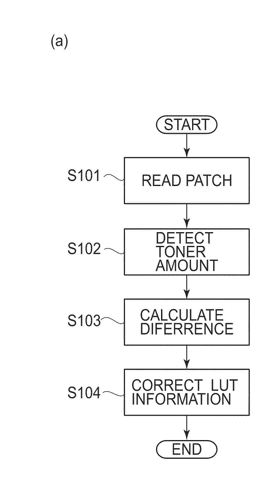
[0095]A schematic constitution of the image forming system and a connection relationship between control portions of the image forming apparatuses will be described. Then, a particular problem when the image is formed by the plurality of image forming apparatuses will be described. Finally, in the case where the present invention is applied to the image forming system, a preferable patch image formation timing control will be described along a flow chart.

1. Image Forming System Constitution

[0096]The constitution in which the transparent image forming app...


PUM


Abstract

An image forming apparatus includes a color image forming portion for forming a color toner image on an image bearing member; a transparent image forming portion for forming a transparent toner image on the image bearing member. The color image forming portion is capable of forming a test color toner image on the image bearing member, and the transparent image forming portion is capable of forming a test transparent toner image on the image bearing member. The apparatus further includes a detecting portion for detecting a density of each of the test color toner image and the test transparent toner image; and a control portion for controlling an image forming condition for an image to be formed on a recording material, on the basis of a result of detection of the density of each of the test color toner image and the transparent toner image. The test transparent toner image and the test color toner image are formed on the image bearing member by the transparent image forming portion and the color image forming portion between an operation for forming the image to be formed on the recording material and a subsequent operation for forming the image to be formed on the recording material. A frequency of formations of the test transparent toner images is lower than that of the formations of the test color toner images.

Description

FIELD OF THE INVENTION AND RELATED ART[0001]The present invention relates to an image forming apparatus utilizing an electrophotographic process, such as a copying machine, a facsimile machine, a printer, or a multi-function machine of these machines.[0002]In recent years, an image forming apparatus for forming an image with color toners of yellow, magenta, cyan, black and the like and for adjusting gloss of the image with transparent toner (clear toner) has been proposed. By using the transparent toner, it is possible to output a silver halide photograph-like image increased in gloss at a whole surface of a photographic original such as human figures or scenic shots or to output a so-called water mark with transparent toner locally formed on a recording material. For example, Japanese Laid-Open Patent Application (JP-A) Sho 63-58374 discloses a method in which a transparent toner image is formed in an area (non-image portion) in which a color toner image is not formed to uniformize...

Claims


Application Information

Patent Timeline
IPC IPC(8): G03G15/00
CPCG03G2215/00059G03G15/5058G03G15/0131G03G2215/00063
Inventor AKITA, MASANORI
Owner CANON KK
Why Eureka
Try Eureka