Sealing system for a water flow control gate

a technology of water flow control and sealing system, which is applied in dams, construction, marine site engineering, etc., can solve the problems of reducing the level of water being held by the gate, reducing or eliminating the usefulness of the gate, and common water leakage between and around the spill-board

Inactive Publication Date: 2011-05-26
WALTHALL BOBBY K
View PDF17 Cites 9 Cited by
  • Summary
  • Abstract
  • Description
  • Claims
  • Application Information

AI Technical Summary

Benefits of technology

[0022]The invention herein is a sealing system for a water flow control gate. Each of a plurality of panels has an upper edge extending the length of the panel with a flat surface rounded upward to a wall at the rear side of the panel. The lower edge of each panel has a central perpendicular foot extending the length of the panel with side flanges and a neck between the central perpendicular foot and the rest of the panel. At each end of each panel is a vertical channel extending across the end of the panel. A horizontal sealing strip on each panel surrounds the central perpendicular foot and extending the length of the panel and a vertical sealing strip is positioned within each vertical channel, so that water flow through the water flow control gate is prevented by the horizontal sealing strips between adjacent stacked panels and by the vertical sealing strips between the ends of each panel and the frame.

Problems solved by technology

When spill-boards are removed, water that was being held behind the spill-boards that have been removed can flow over the remaining spill-boards, thus lowering the level of water being held by the gate.
Because the spill-boards must be removable to allow adjustment of the water level behind the gate, and because the water behind the gate, where the water is higher than in front of the gate, is pushing against the spill-boards, water leakage between and around the spill-boards is a common problem.
At its extreme, the leakage through the gated area can greatly reduce or eliminate the usefulness of the gate.
This problem, of course, is not confined to sluice gates and can occur whenever a multi-part door or gate is being used to keep water from flowing.
While many of the prior sealing mechanisms increase the water-holding capacity of particular water flow control gates, there remains a need for a sealing system that both impedes water flow between the stacked boards in a water flow control gate and impedes flow of water around the sides of the stacked boards where the boards are held in a guide way or frame.

Method used


Image

  • Sealing system for a water flow control gate
  • Sealing system for a water flow control gate
  • Sealing system for a water flow control gate

Examples


Embodiment Construction

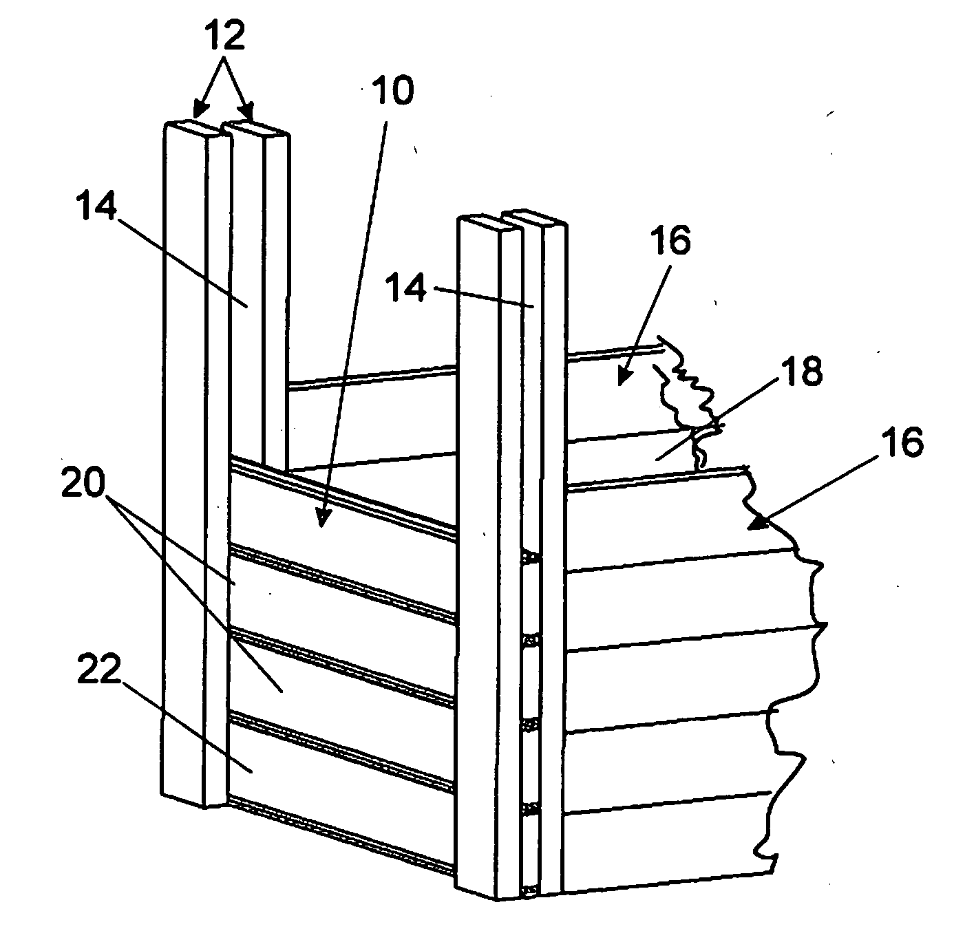
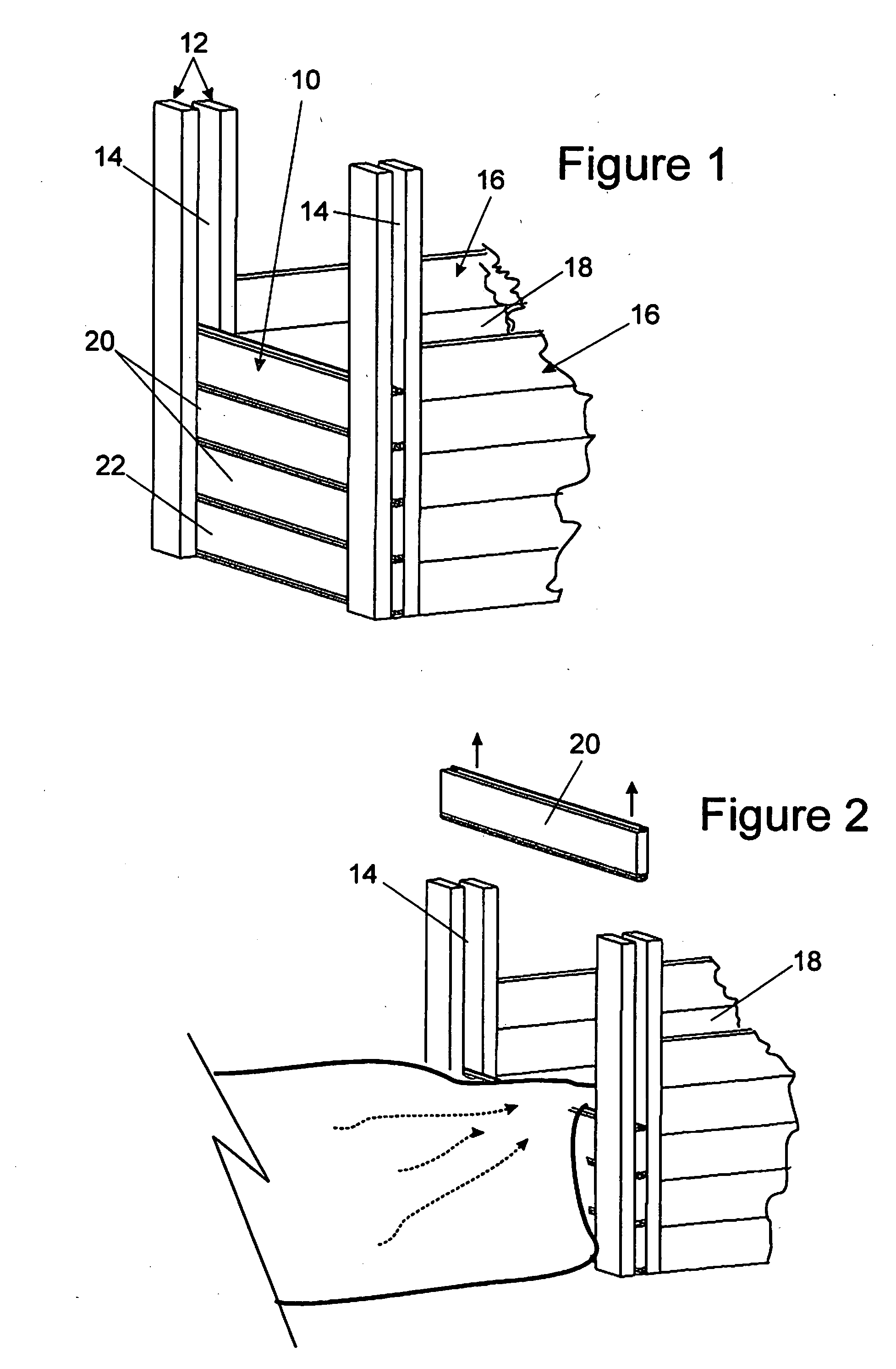
[0035]The present invention provides a sealing system for a water flow control gate. As used herein the term “water flow control gate” refers to any gate which has removable panels, such as stacked horizontal spill-boards that together form a flat face, and that are held in place in a vertical guide way or frame on each end of the spill-boards, and includes sluice gates, flume gates, stoplog gates, slide gates or penstocks or other comparable gates having a comparable function. Generally such water flow control gates also have a cross-bar structure at their top to hold the vertical guide way or frame on the two sides of the channel together.

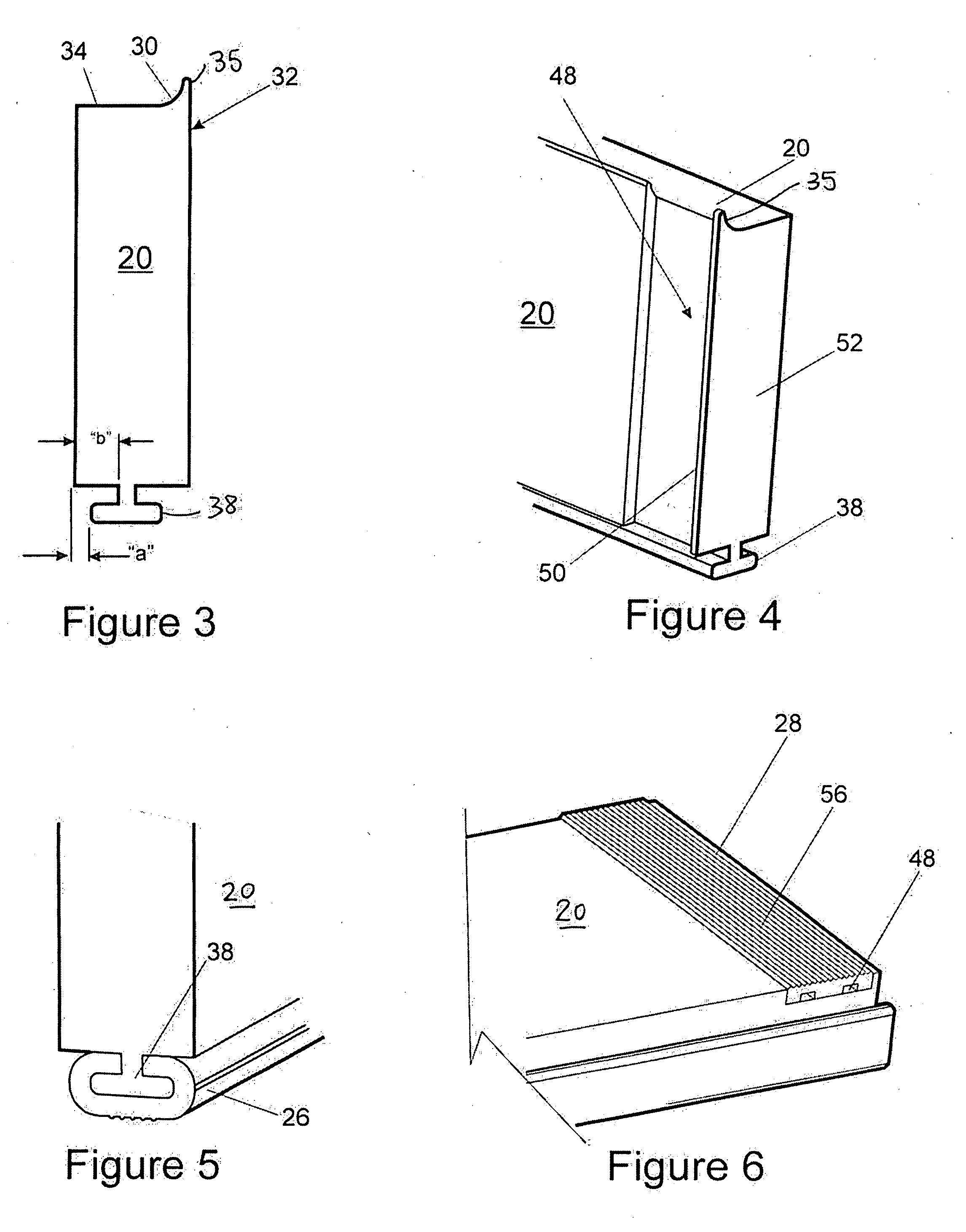
[0036]In particular, the invention herein is a sealing system for a water flow control gate, and a water flow control gate having the sealing system of the invention on each panel forming the gate. Each of a plurality of panels has an upper edge extending the length of the panel with a flat surface rounded upward to a rear side of the panel. The ...


PUM


Abstract

A sealing system for a water flow control gate is provided. Each of a plurality of panels has an upper edge extending the length of the panel with a flat surface rounded upward to a wall at the rear side of the panel. The lower edge of each panel has a central perpendicular foot extending the length of the panel with side flanges and a neck between the central perpendicular foot and the rest of the panel. At each end of each panel is a vertical channel extending across the end of the panel. A horizontal sealing strip on each panel surrounds the central perpendicular foot and extending the length of the panel and a vertical sealing strip is positioned within each vertical channel, so that water flow through the water flow control gate is prevented by the horizontal sealing strips between adjacent stacked panels and by the vertical sealing strips between the ends of each panel and the frame.

Description

BACKGROUND OF THE INVENTION[0001]1. Field of the Invention[0002]This invention relates to water flow control gates, and in particular relates to a sealing system for the components of sluice gates and the like.[0003]2. Description of the Related Art[0004]Water flow control gates (also known in various applications, for example, as sluice gates, flume gates, stoplog gates, slide gates or penstocks) are used selectively to control water flow from one area of a channel to another by opening or closing off the channel to the water flow.[0005]In cranberry bogs, such gates allow control of flooding and draining operations, which are used to protect the crop from frost and to change water levels during the harvest of the cranberries. An early flume gate for cranberry bogs is provided by Whipple (U.S. Pat. No. 2,530,747). Typically, the flume gates as used in the cranberry industry comprise a series of stacked contiguous horizontal panels or spill-boards that together form a flat face. The ...

Claims


Application Information

Patent Timeline
Patent Type & Authority Applications(United States)
IPC IPC(8): E02B7/34
CPCE02B7/54E02B7/34
Inventor WALTHALL, BOBBY K.
Owner WALTHALL BOBBY K
Why Eureka
Try Eureka