Floatable pump unit

a floating pump and pump technology, applied in the direction of pump components, pump control, non-positive displacement fluid engines, etc., can solve the problems of significant increase in the danger of solid matter penetrating into the pump through the inlet opening and clogging the pump, and the application of such pumps is problematic, so as to achieve at least significant reduction of the clogging of the pump assembly

Inactive Publication Date: 2011-05-26
GRUNDFOS MANAGEMENT AS
View PDF10 Cites 17 Cited by
  • Summary
  • Abstract
  • Description
  • Claims
  • Application Information

AI Technical Summary

Benefits of technology

[0004]Against this background, it is an object of the present invention to provide a buoyant pump assembly which is suitable for the applicati

Problems solved by technology

The application of such pumps has been found to be problematic, if the containers or waters are formed in a closed manner, and the fluids to be sucked are intermingled with solid matter particles.
By way of this, the

Method used


Image

  • Floatable pump unit
  • Floatable pump unit
  • Floatable pump unit

Examples


Embodiment Construction

[0030]Certain terminology is used in the following description for convenience only and is not limiting. The words “lower,”“bottom” and “top” designate directions in the drawings to which reference is made. The word “outwardly” refers to a direction away from the geometric center of the device, and designated parts thereof, in accordance with the present invention. Unless specifically set forth herein, the terms “a,”“an” and “the” are not limited to one element, but instead should be read as meaning “at least one.” The terminology includes the words noted above, derivatives thereof and words of similar import.

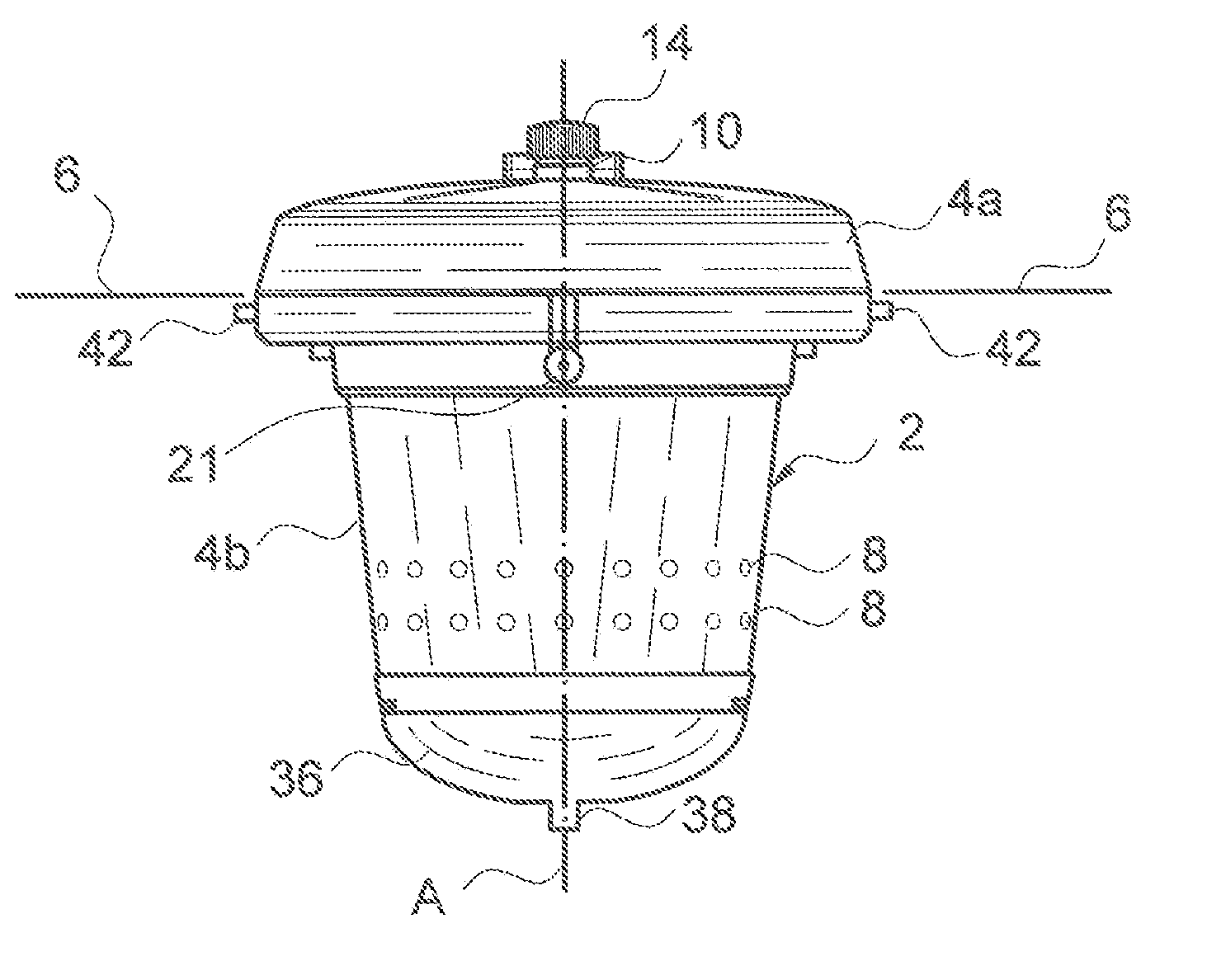
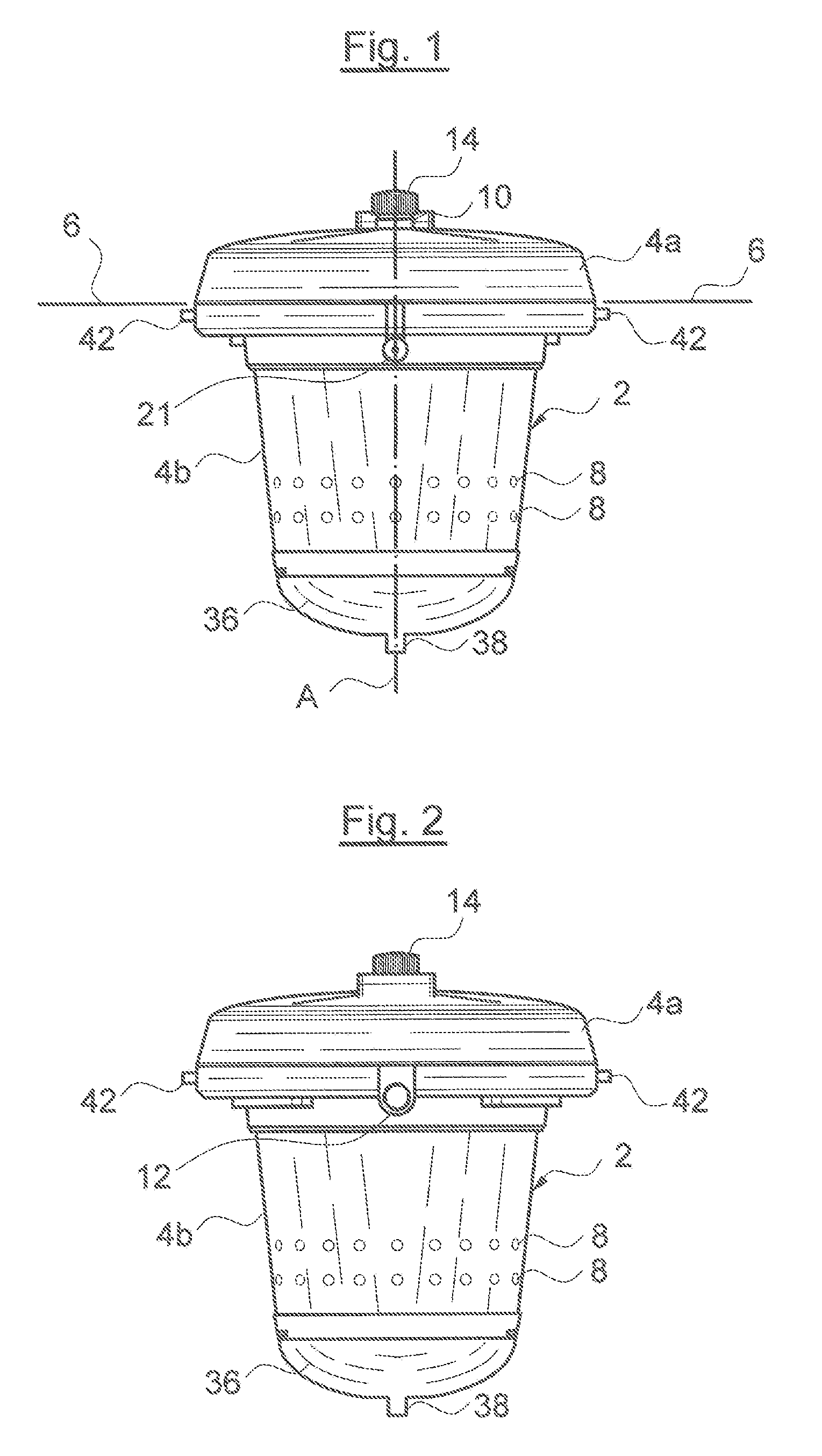
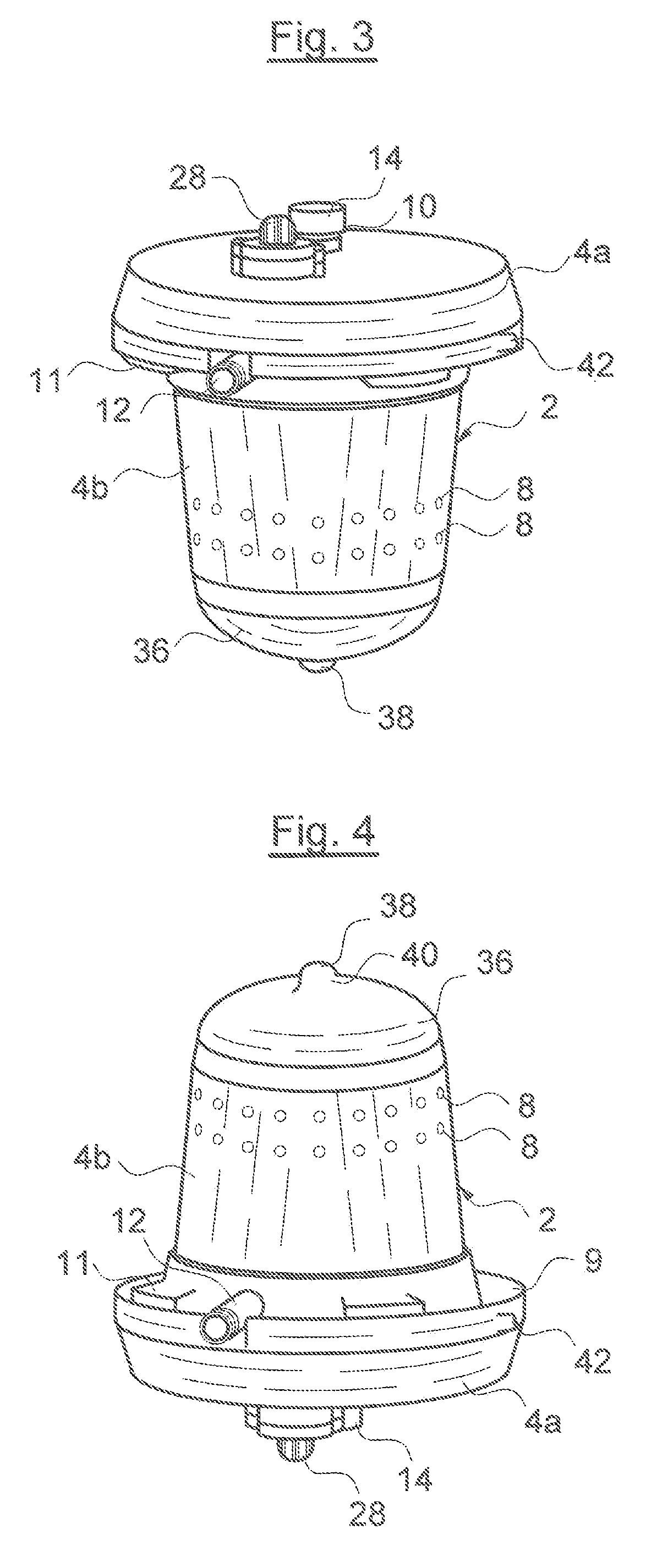
[0031]Referring to the drawings in detail, wherein like numerals indicate like elements throughout the several views, FIGS. 1-9 show a pump assembly according to a preferred embodiment of the present invention. The pump assembly preferably comprises an assembly housing 2. The pump assembly is designed in a floating manner, wherein an assembly housing part 4a, to the most part, ...


PUM


Abstract

A pump assembly is buoyant and includes an electrical drive motor (16), a centrifugal pump driven by the motor, and an assembly housing (2) accommodating the drive motor (16) and the centrifugal pump. Moreover, the pump assembly includes at least one inlet opening (8) which is arranged below the fluid surface (6) in the floating condition, and at least one outlet opening (10, 12). The assembly housing (2) is arranged such that on reaching a contact surface, the assembly housing changes its alignment with respect to the floating position.

Description

CROSS-REFERENCE TO RELATED APPLICATIONS[0001]This application is a Section 371 of International Application No. PCT / EP2009 / 001261, filed Feb. 21, 2009, which was published in the English language on Sep. 11, 2009, under International Publication No. WO 2009 / 109305 A3 and the disclosure of which is incorporated herein by reference.BACKGROUND OF THE INVENTION[0002]The present invention relates to a buoyant pump assembly, with the features specified in the preamble of the independent claim(s).[0003]Buoyant pumps, which, floating on the fluid surface of containers and waters, suck fluid or water from these containers and waters, are counted as belonging to the state of the art. The application of such pumps has been found to be problematic, if the containers or waters are formed in a closed manner, and the fluids to be sucked are intermingled with solid matter particles. The reason for this is due to the fact that these pumps sink into a region of the container or water which is close t...

Claims


Application Information

Patent Timeline
IPC IPC(8): F04B53/00
CPCF04D29/426F04D13/08F04D13/066F04D15/0218F04D15/0272
Inventor LEONE, MICHELEDAL CANTO, RICCARDOWIATR BORG, SUSANNE
Owner GRUNDFOS MANAGEMENT AS
Why Eureka
Try Eureka