Localization of capsule with a synthetic source of quadrupoles and dipoles

a synthetic source and capsule technology, applied in the field of in vivo system for localizing an autonomous in vivo imaging device, can solve the problems of difficult to measure the relative location and orientation of the physical space and/or electronic resources that can be allocated for the source and/or the sensor are extremely limited, and the need to have a precise knowledg

Active Publication Date: 2011-05-26
GIVEN IMAGING LTD
View PDF21 Cites 35 Cited by
  • Summary
  • Abstract
  • Description
  • Claims
  • Application Information

AI Technical Summary

Benefits of technology

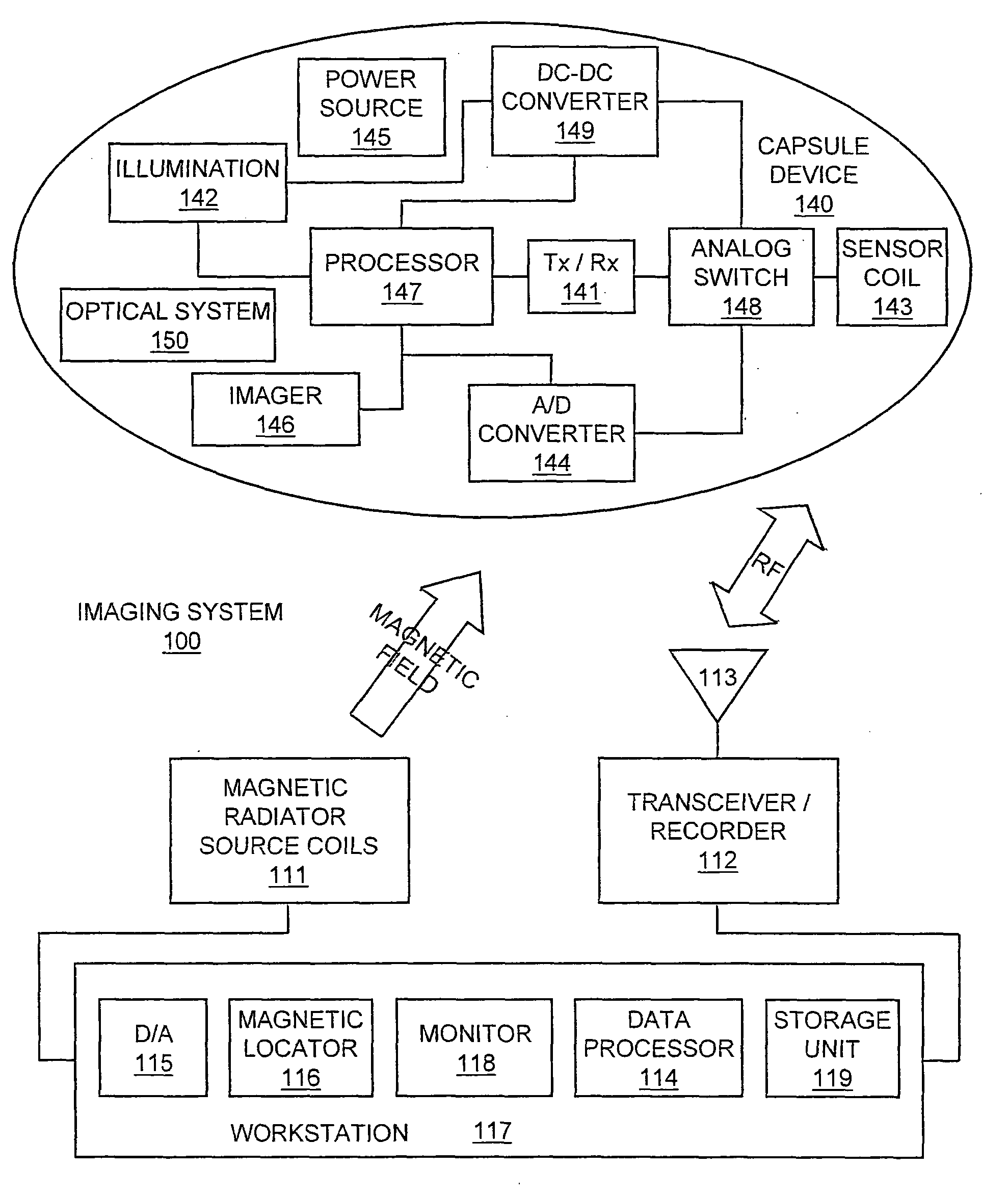
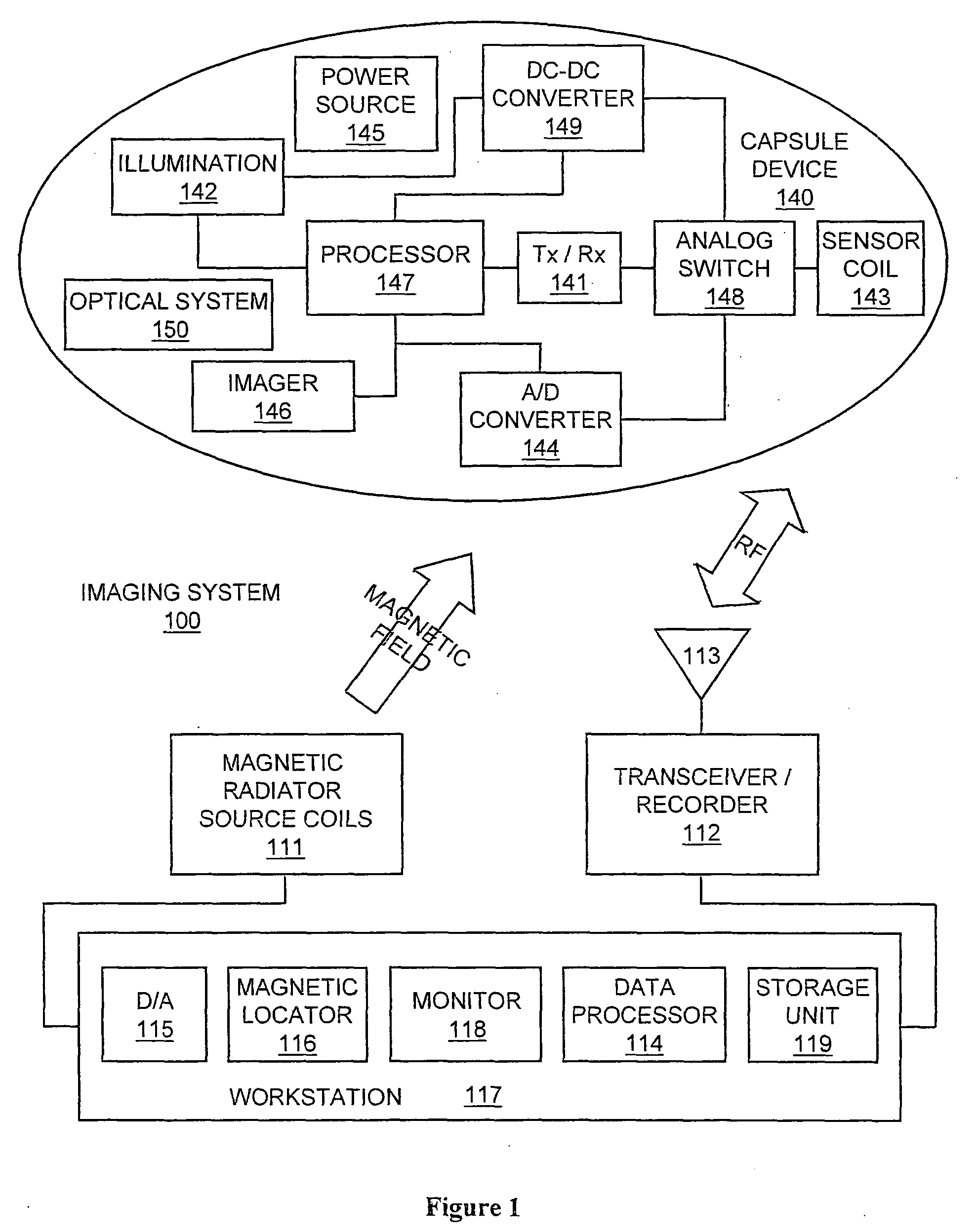
[0018]A data processor may analyze the data received via external transceiver/recorder from device, and may be in communication with storage unit, e.g., transferring frame data to and from storage unit. Data processor may provide the analyzed data to monitor, where a user (e.g., a physician) may view or otherwise use the data. Monitor may include, for example, one or more screens, monitors, or suitable display units. Typically, the device may tran

Problems solved by technology

However, in many applications the physical space and/or electronic resources that can be allocated for a source and/or a sensor are extremely limited.
The main disadvantage of this approach is the need to have a

Method used


Image

  • Localization of capsule with a synthetic source of quadrupoles and dipoles
  • Localization of capsule with a synthetic source of quadrupoles and dipoles
  • Localization of capsule with a synthetic source of quadrupoles and dipoles

Examples


Embodiment Construction

schematic depictions of reconstructed trajectories with various levels of noise according to an embodiment of the present invention;

[0029]FIG. 15 is a graphic depiction of reconstruction trajectory quality under noisy data according to an embodiment of the present invention;

[0030]FIG. 16 is a schematic depiction of reconstructed trajectory using the robust algorithm, according to embodiments of the present invention; and

[0031]FIG. 17 is a schematic depiction of the reconstructed trajectory of FIG. 16 but with a scan resolution of 0.5°, according to embodiments of the present invention.

[0032]It will be appreciated that for simplicity and clarity of illustration, elements shown in the figures have not necessarily been drawn to scale. For example, the dimensions of some of the elements may be exaggerated relative to other elements for clarity. Further, where considered appropriate, reference numerals may be repeated among the figures to indicate corresponding or analogous elements.

DETA...


PUM


Abstract

This invention relates to methods and apparatus for localizing an in vivo imaging device by means of a single magnetic source coil assembly and a single magnetic detector coil assembly. This invention also relates to methods and apparatus to enable the use of a single magnetic source coil assembly to also transmit and receive information, images, and controls signals, as well as for the coil assembly to be used in DC-DC voltage conversion. A user interface with a display provides the user with the option of viewing selected images captured by the in vivo imaging device.

Description

FIELD OF INVENTION[0001]The present invention relates to an in vivo device and method such as for imaging an in vivo lumen. More specifically, the present invention relates to a method and apparatus for an in vivo system for localizing an autonomous in vivo imaging device.BACKGROUND OF THE INVENTION[0002]Known devices may be helpful in providing in vivo sensing, such as imaging or pH sensing. Autonomous in vivo sensing devices, such as swallowable or ingestible capsules or other devices may move through a body lumen, sensing as they move along. An autonomous in vivo sensing device such as an imaging device may include, for example, an imager for obtaining images from inside a body cavity or lumen, such as the gastrointestinal (GI) tract while the in vivo imaging device passes through the GI lumen. The imager may, for example, be associated with an optical system, and optionally a transmitter and an antenna. Some of these devices use a wireless connection to transmit image data. Othe...

Claims


Application Information

Patent Timeline
IPC IPC(8): A61B5/05
CPCA61B1/00016A61B1/00029A61B1/00032A61B2560/0219A61B1/041A61B1/0684A61B5/06A61B1/00158A61B5/062
Inventor STEINBERG, BEN ZIONBETTESH, IDO
Owner GIVEN IMAGING LTD
Why Eureka
Try Eureka