Injection Needle Assembly

Active Publication Date: 2011-05-26
SHL MEDICAL AG
View PDF8 Cites 2 Cited by
  • Summary
  • Abstract
  • Description
  • Claims
  • Application Information

AI Technical Summary

Benefits of technology

[0015]There are a number of advantages with the present invention. Because the needle assembly comprises three components, the cap, the needle holder, and the needle cover, wherein the cap and needle holder are displaceable and lockable in relation to each other, and wherein the cap and the needle cover are displaceable and lockable in relation to each other; the injection needle could easily be moved from one position where it is not in contact with

Problems solved by technology

This could be a drawback if the medicament reacts with the material of the needle when exposed for a period of time.
After this the container and the needle is advanced further, causing a penetration of the patient's skin.
The above mentioned injectors require a lot of components and it is relatively complicated to sterilize the injection needle and keep it sterile.
Further, for multi-dose injectors requiring a needle change before each injection, the above mentioned solutions cannot be used.
In '742, the needle holder is distally displaced by merely gripping a surrounding needle sheath that is of a flexible material, such as rubber, thereby providing a risk of accidental needle sticks.
Further, there is no locking/preventing means between

Method used


Image

  • Injection Needle Assembly
  • Injection Needle Assembly
  • Injection Needle Assembly

Examples


Embodiment Construction

[0028]In the present application, when the term “distal part / end” is used, this refers to the part / end of the assembly, or the parts / ends of the members thereof, which is / are located the furthest away from the medicament delivery site of the patient. Correspondingly, when the term “proximal part / end” is used, this refers to the part / end of the assembly, or the parts / ends of the members thereof, which, is / are located closest to the medicament delivery site of the patient.

[0029]The present invention is intended to be used in medicament injection devices, which could be of any type from simple manual injectors to multi-function auto-injectors. However they do not form part of the present invention and are thus not shown in the drawings.

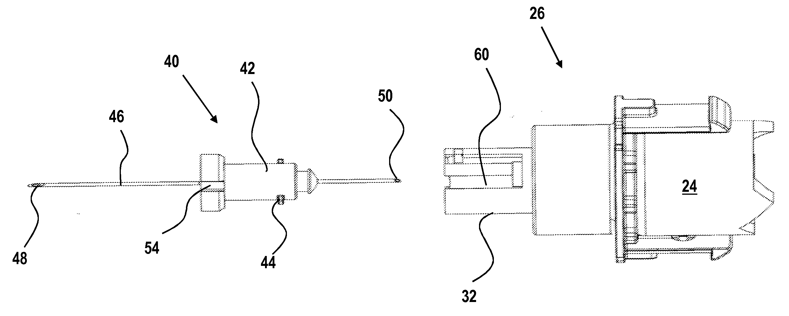
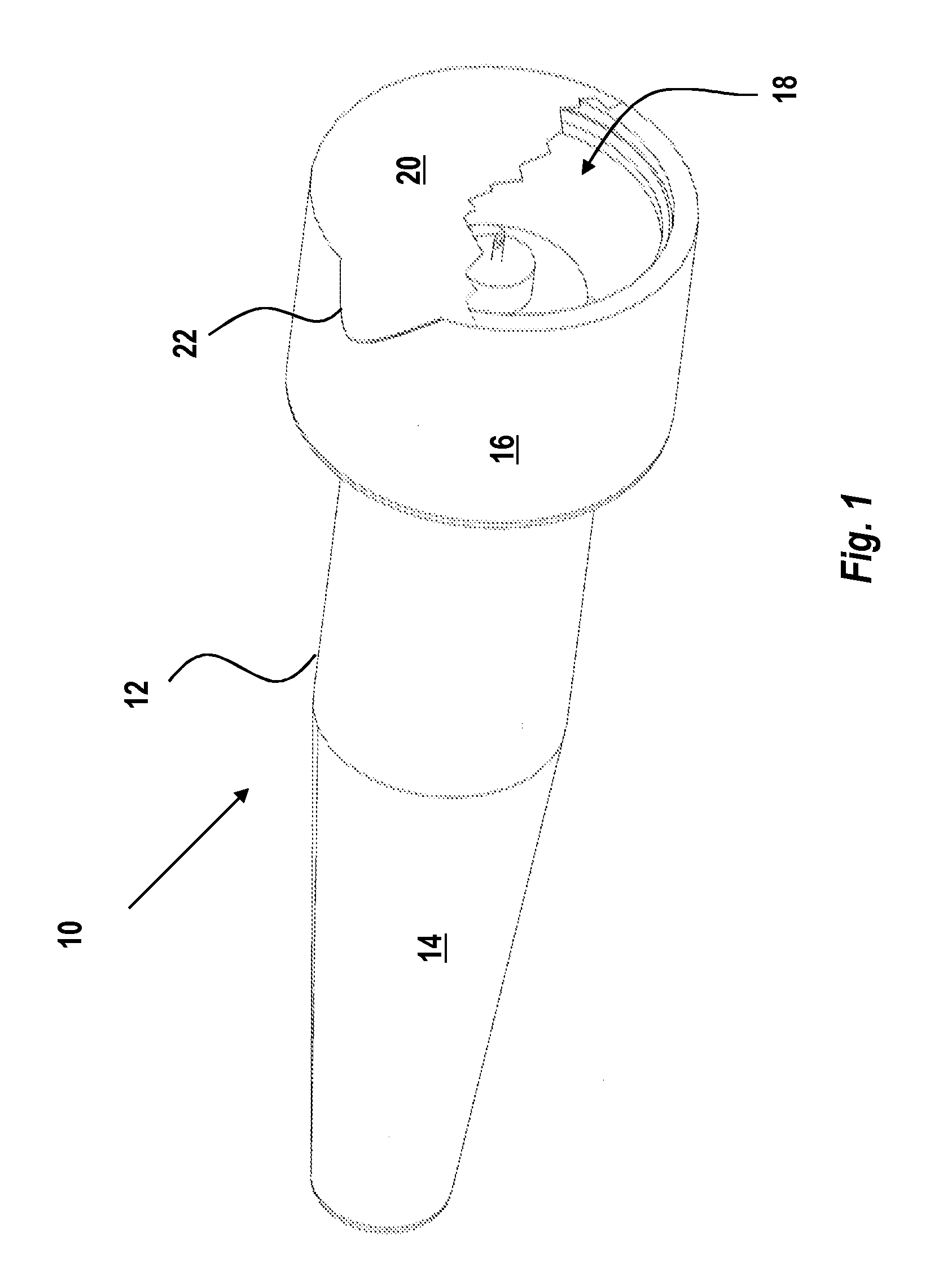
[0030]FIG. 1 shows a needle assembly 10 having opposite distal and proximal ends according to the present invention. The assembly comprises an injection needle 46 having proximal 48 and distal 50 pointed ends, wherein the distal pointed end is arranged t...


PUM


Abstract

The present invention relates to an injection needle assembly having opposite distal and proximal ends, and wherein the assembly comprises an injection needle (46) having proximal (48) and distal (50) pointed ends, wherein the distal pointed end is arranged to penetrate a membrane arranged at the proximal end of a medicament container; a tubular needle holder (40) comprising distal engagement means (44; 70) and proximal engagement means (54); a tubular cap (26) comprising proximal outer engagement means (60; 80) and proximal inner engagement means (36, 38; 72); a tubular needle cover (12) comprising first engagement means (52) arranged to cooperate with the proximal engagement means (54), and second engagement means (58; 78) arranged to cooperate with the proximal outer engagement means (60; 80) of the cap; characterized in that said needle cover is arranged to be displaced from a first position wherein the second engagement means (58; 78) and the proximal outer engagement means (60; 80) prevents the needle cover and the needle holder to be axially displaced by a linear displacement, to a second position wherein the needle cover and the needle holder are distally displaced, and wherein the proximal inner engagement means (36, 38; 72) of the cap and the distal engagement means (44; 70) of the needle holder prevents the needle holder to be proximally displaced but allows the needle cover to be distally displaced.

Description

TECHNICAL AREA[0001]The present invention relates to an injection needle for medical devices, and in particular sterile aspects of handling injection needles.BACKGROUND OF THE INVENTION[0002]Many medicament delivery devices such as injectors are often developed for self-administration, i.e. the user performs the injection. In order to have a simple handling of the device it is often desirable to have it as pre-assembled as possible. Therefore often the injector is delivered to the user with an injection needle pre-attached.[0003]Another aspect of attachment of injection needles to medicament containers is that the rear end of the injection needle often protrudes into the interior of the container. This could be a drawback if the medicament reacts with the material of the needle when exposed for a period of time. In that respect it would be desirable to have the rear part of the needle outside the container until the injection is to be performed. On the other hand, this then requires...

Claims


Application Information

Patent Timeline
IPC IPC(8): A61M5/00
CPCA61M5/3204A61M5/3202A61M5/2466A61M5/347A61M2005/2474A61M5/3286
Inventor GIAMBATTISTA, LUCIODE SALVO, DAVIDBENDEK, ANTONIO
Owner SHL MEDICAL AG
Why Eureka
Try Eureka