Power generation apparatus
a power generation apparatus and power technology, applied in mechanical equipment, motors, machines/engines, etc., can solve the problems of reducing power generation efficiency and inability to generate power, and achieve the effects of enhancing power generation efficiency, and generating power reliably
- Summary
- Abstract
- Description
- Claims
- Application Information
AI Technical Summary
Benefits of technology
Problems solved by technology
Method used
Image
Examples
first embodiment
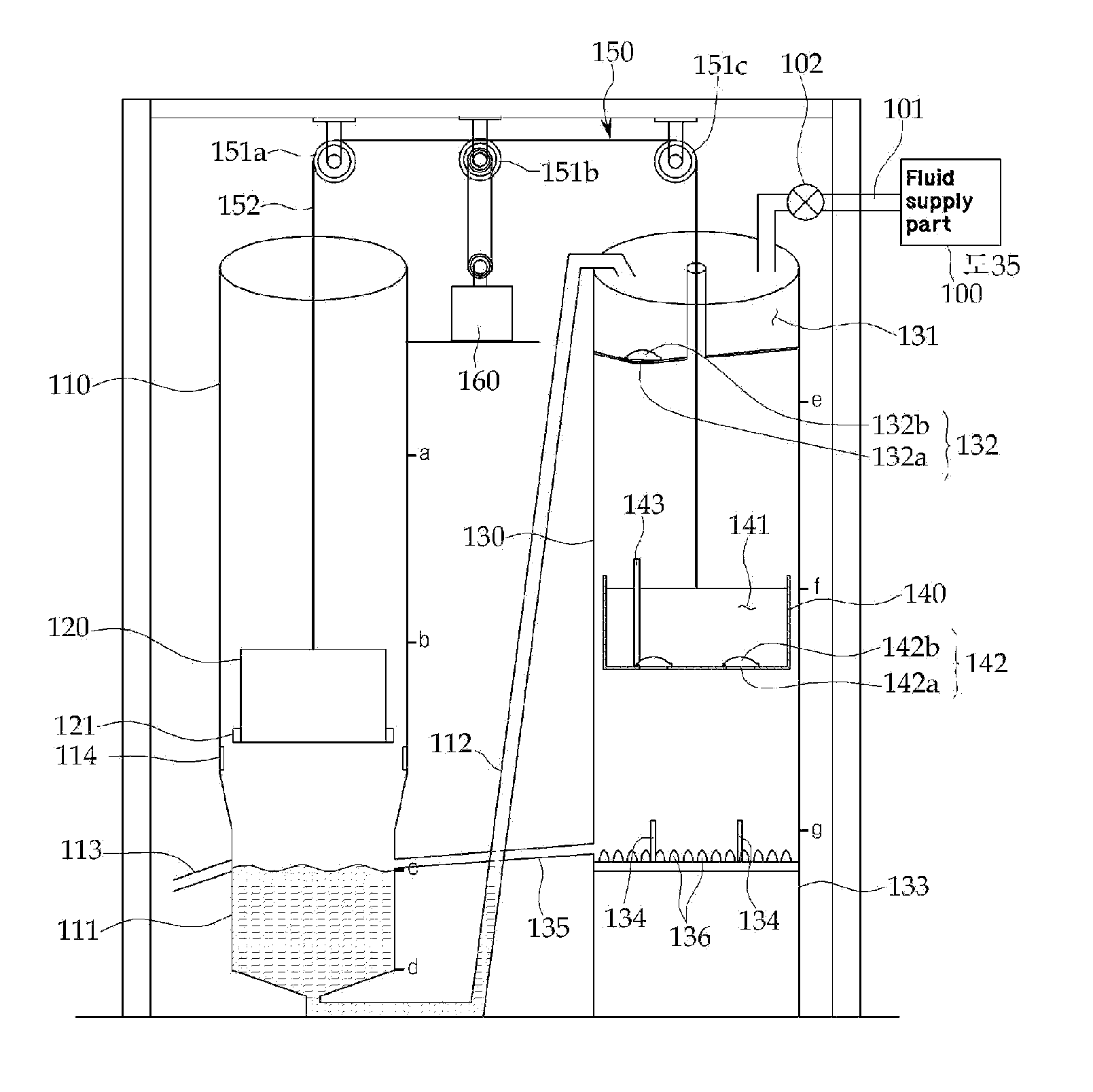
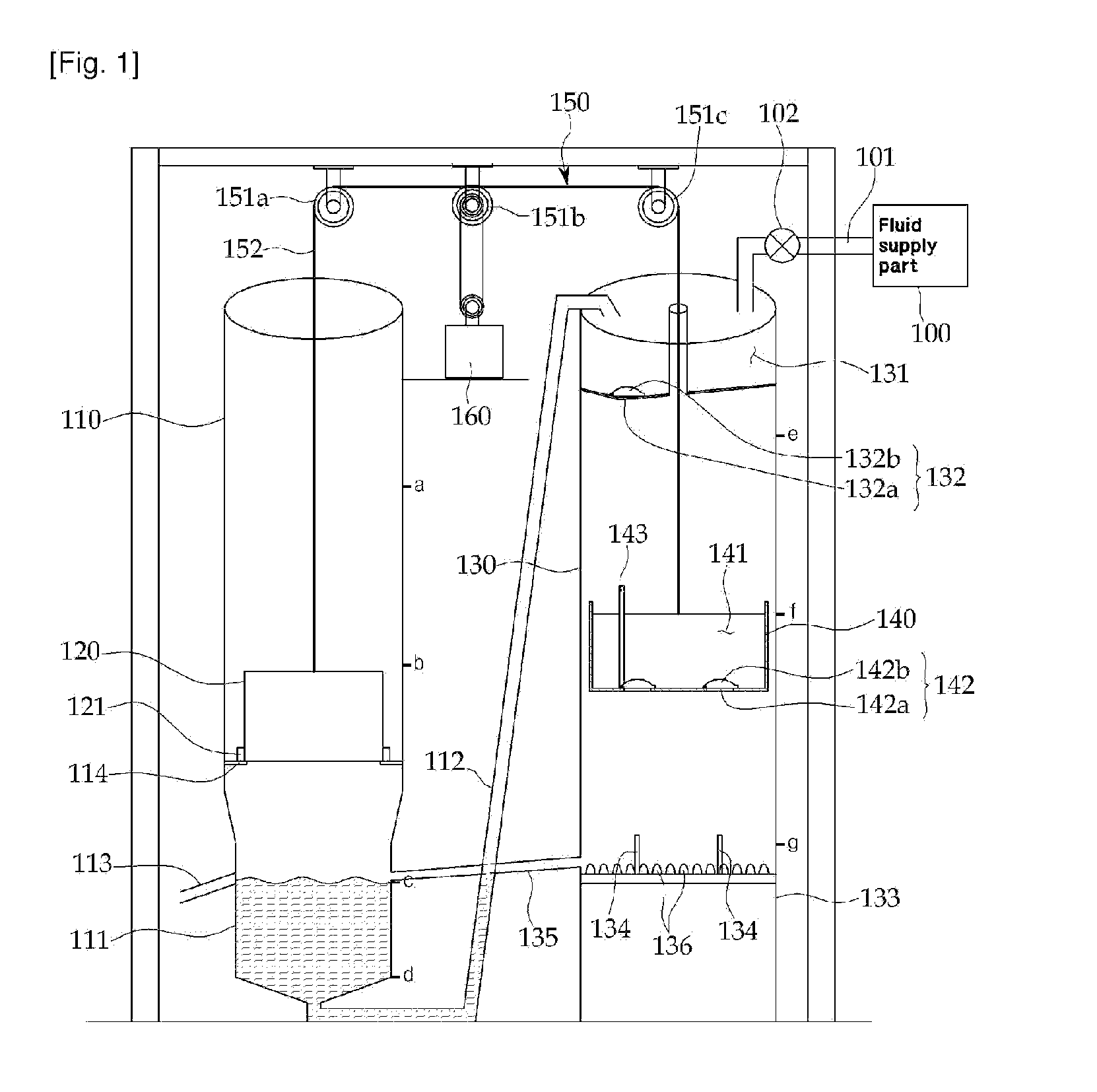
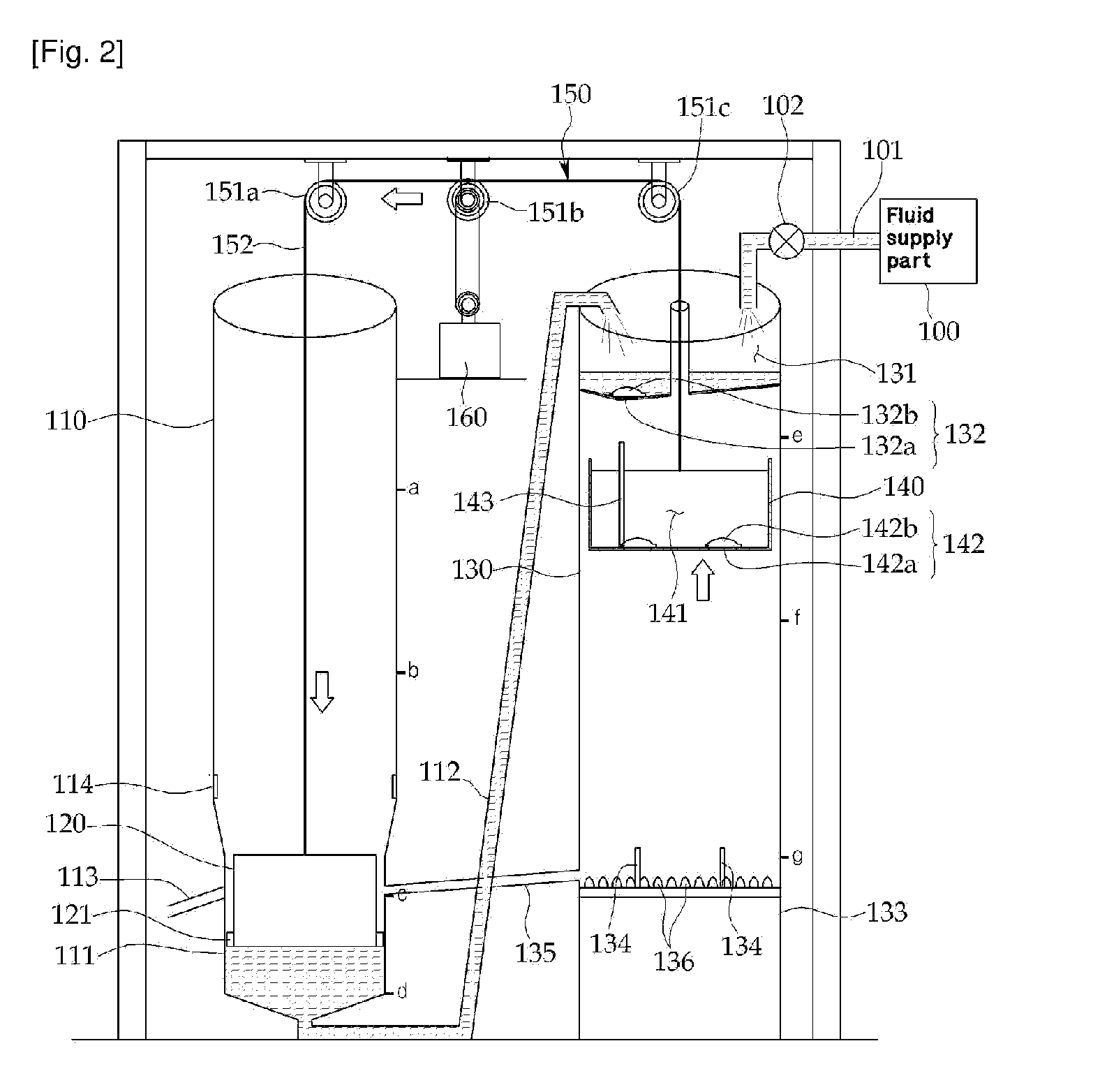
[0052]As shown in FIG. 1, the power generation apparatus according to the present invention comprises a weight load guide box 110, a weight load 120 which is movable up and down in the interior of the weight load guide box 110, a movable storage tank guide box 130 disposed close to the weight load guide box 110, a movable storage tank 140 which is movable in up and down directions in the interior of the movable storage tank guide box 130, and a power transfer unit 150 which drivingly connects the weight load 120 and the movable storage tank 140.
[0053]The weight load guide box 110 guides the up and down movements of the weight load 120. A fluid transfer part 111 is provided at a lower side of the weight load transfer guide box 110, and the fluid transfer part 111 is connected with the movable storage tank guide box 130 via a transfer pipe 112 and is connected with a fluid discharge part 133 of a lower side of the movable storage tank guide box 130 via a retrieval pipe 135. The fluid ...
second embodiment
[0078]FIGS. 9 to 20 are schematic views of a power generation apparatus according to the present invention.
[0079]As shown in FIG. 9, the power generation apparatus according to a second embodiment of the present invention, as compared to the first embodiment of the present invention, the structure of the fluid transfer part 211 has been changed, and the supply maintaining unit 270 and the discharge maintaining unit 280 are further added, and the brake apparatus 290 is further added to limit the movement of a supply maintaining wire 152. Since the structures and operations are same as the first embodiment except for the above mentioned differences, only the different matters will be described. In the following descriptions, while the second embodiment is described, the same elements as the first embodiment will be given the same reference numerals in the second embodiment of the present invention.
[0080]As shown in FIGS. 9 and 10, the fluid transfer part 211 comprises a contractible m...
third embodiment
[0100]FIGS. 21 and 22 are schematic views of the major elements of the power generation apparatus according to the present invention.
[0101]As shown in FIG. 21, the power generation unit 350 of the power generation apparatus according to a third embodiment of the present invention comprises a plurality of power transfer gears 351a, 351b, 351c and 351d, and first and second rack gears 352 and 353, which are different from the first and second embodiments of the present invention.
[0102]The lower side of the first rack gear 352 is fixed to the weight load 120, and the lower side of the second rack gear 353 is fixed to the movable storage tank 140. The first and second rack gears 352 and 353 are engaged with the power transfer gears 351a, 351b, 351c respectively. The numbers of the power transfer gears 351a, 351b, 351c are determined in such a manner that the first and second rack gears 352 and 353 are to move in opposite directions from each other. Namely, an odd number of the power tra...
PUM
 Abstract
Description
Claims
Application Information
 - R&D
- Intellectual Property
- Life Sciences
- Materials
- Tech Scout
- Unparalleled Data Quality
- Higher Quality Content
- 60% Fewer Hallucinations
Browse by: Latest US Patents, China's latest patents, Technical Efficacy Thesaurus, Application Domain, Technology Topic, Popular Technical Reports.
© 2025 PatSnap. All rights reserved.Legal|Privacy policy|Modern Slavery Act Transparency Statement|Sitemap|About US| Contact US: help@patsnap.com


