
Container for housing a tray or blister pack

a container and tray technology, applied in the field of containers, can solve the problems of information) and/or the limited or inconvenient housing of a leaflet or bookl

Active Publication Date: 2011-06-02
WESTROCK MWV LLC
View PDF30 Cites 13 Cited by
  • Summary
  • Abstract
  • Description
  • Claims
  • Application Information

AI Technical Summary

Benefits of technology

[0011]A blister pack generally comprises a generally planar side formed by a foil (typically of aluminium) and a plastic layer having one or more blisters moulded therein. Each blister comprises an enclosure with an open side which is covered by the foil. Articles (such as pills) housed in said blisters can be ejected through the foil by pressing the relevant blister. Perforations may be provided in the foil in the area of each blister to facilitate rupture of a localised area of the foil as an article is ejected from a blister.
[0030]As will be described further below, the container provides several advantages over prior art containers such as those mentioned above. In certain embodiments, a standard blister pack can be accommodated, that is, having no special features other than conventional blisters mounted on a planar substrate with at least a portion of some edges extending beyond the blisters. In certain embodiments, the shell of the container may incorporate indents, tabs, or other devices that have a loose interference fit with the blisters themselves or with other features of the tray or blister pack so as to allow the tray or blister pack to be indexed by steps out of the shell. In certain embodiments, the shell is provided with an access or cutout area by which to move the tray or blister pack out of or into the shell. In certain embodiments, portions of the shell may be formed to allow a close sliding fit with the edges of the tray or blister pack to provide a smooth sliding action and secure retention of the tray or blister pack against unwanted motion within the container.

Problems solved by technology

These containers suffer from various disadvantages: provisions for the display of compliance information (or other information) and / or the housing of a leaflet or booklet may be limited or inconvenient, and their manufacture requires the use of a relatively large amount of paperboard or plastic material in order to form a sturdy container.

Method used


Image

  • Container for housing a tray or blister pack
  • Container for housing a tray or blister pack
  • Container for housing a tray or blister pack

Examples


first embodiment

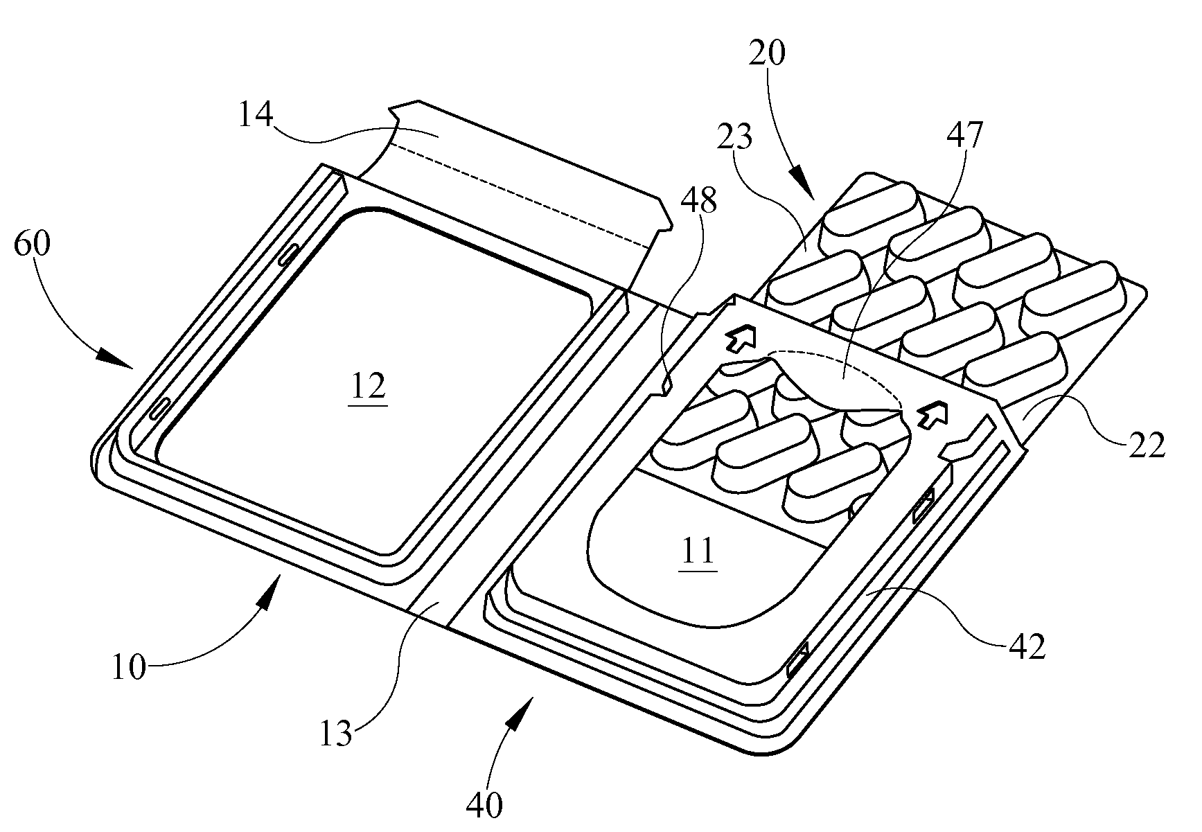
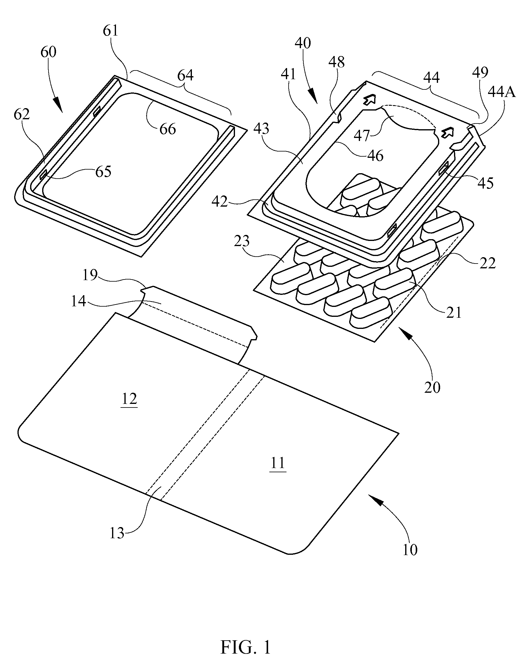
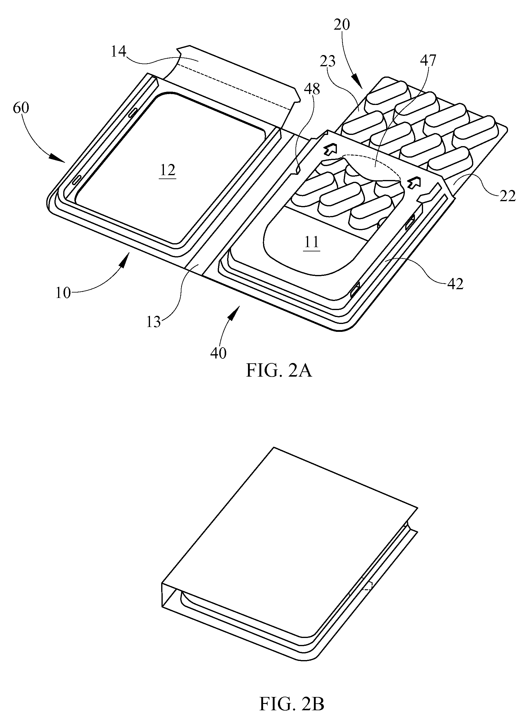
[0049]FIGS. 1, 2A and 2B show a container comprising a cover 10, a shell 40, and a frame 60. The cover 10 may be formed from a sheet material such as paperboard, and comprises a base portion 11, a lid portion 12 and a hinge portion 13 that connects the base portion 11 to the lid portion 12 at first and second fold lines. A structure similar to a book cover is thus formed, which may be printed on one or both sides. Attached to one edge of lid 12 is a closure flap 14 with a closure tooth 19 (although, as described further below, this flap may be omitted in some embodiments).

[0050]A shell portion 40 is provided that may be a thermoformed plastic or pressed paperboard structure. The shell portion 40 may also be provided by other means such as, for example, injection moulding. The shell portion attached to the base portion thus forms a sheath for holding contents within this container and other containers disclosed herein. The shell portion 40 has a shell sealing surface 41, for example,...

sixth embodiment

[0077]FIGS. 7A and 7B show the container. This embodiment is similar to that of FIGS. 6A and 6B except for the provision of a different form of indexing elements. In this case, a series of indents 540D are provided along the opposite sides of the shell 540 which are resiliently engaged by the wedge-shaped projections 520B and 520C (see FIG. 9) on the blister pack 520 as these are slid past the indents 540D. For this purpose, the outer sides of the wedge-shaped projections 520B and 520C are preferably curved as shown in FIG. 9. FIG. 7B shows this container when in the closed configuration.

[0078]FIG. 8 shows a blister pack 420 such as that used in the container shown in FIGS. 6A and 6B. In addition to the blister for housing pills, this has an upstanding wall 420D for closing the outlet of the container as described above. It also has two wedge-shaped projections 420B and 420C for providing the second locking feature described above, i.e., to prevent complete withdrawal of the blister...

seventh embodiment

[0084]FIGS. 10 to 14 show the container. The container of this embodiment is formed entirely from foldable sheet material such as cardboard, paperboard, corrugated board, plastic, paper-plastic composite material or the like. FIG. 10 illustrates a blank 610 as viewed from its inside surface, from which the container of this embodiment is formed. The blank 610 may be printed on one or both sides. The blank 610 comprises a base portion 611, a lid portion 612, a hinge portion 613 and a shell portion 640. The hinge portion 613 connects the base portion 611 to the lid portion 612 at first and second fold lines 671 and 672.

[0085]The base portion 611 includes a primary base panel 673, a first upper closure flap 674 and a first lower closure flap 675. The upper and lower closure flaps 674, 675 are hingedly connected to the primary panel 673 along a tear line 676 and a fold line 677 respectively.

[0086]The lid portion 612 includes an outer lid panel 660, an outer side panel 661, an inner side...


PUM


Abstract

A container includes a base portion (11), a lid portion (12), and a hinge portion (13) connecting the base portion to the lid portion. The lid portion and / or the base portion are movable about the hinge portion between an open configuration and a closed configuration in which the lid portion overlies the base portion substantially in the form of a book. The base portion has a shell (40) attached thereto to form a sheath for receiving one or more articles (20). The sheath has an open end or outlet (44) and allows one or more articles to slide relative thereto in the direction substantially parallel to the base portion between a storage position and one or more dispensing positions.

Description

BACKGROUND OF THE INVENTION[0001]This disclosure relates to a container and, more particularly, a booklet-style container for housing an article such as a tray or blister pack. It also relates to a blister pack for housing in the container.[0002]A wide variety of containers are known for holding blister packs, e.g. containing an array of pills. Commonly, the blister pack is enclosed in a carton, e.g. a cardboard container one end of which opens to enable the blister pack to be inserted therein and removed therefrom. Similarly there are containers for holding other objects such as medical devices, for example syringes, where the syringes may be held in thermoformed trays or tray structures made of paperboard.[0003]A tray or blister pack may also be provided in a plastic sheath which is closed on three sides but open at one end. Examples of such sheaths are described in WO2004 / 037657, WO2005 / 030606 and WO2005 / 049448.[0004]These containers suffer from various disadvantages: provisions ...

Claims


Application Information

Patent Timeline
IPC IPC(8): B65D77/00B65D25/54B65D5/66
CPCA61J1/035A61J7/04A61J1/03B65D83/0463B65D77/006B65D77/0446B65D83/04
Inventor SAMS, STEPHENFRASER, ANTHONYLOFTIN, CALEB S.
Owner WESTROCK MWV LLC
Learn More