Power converter

a power converter and converter technology, applied in the field of power converters, can solve the problems of inverter circuit lengthening, short circuit switch on time, conventional technology, etc., and achieve the effect of promoting device structure size reduction and reducing power loss and nois

Active Publication Date: 2011-06-02
MITSUBISHI ELECTRIC CORP
View PDF1 Cites 13 Cited by
  • Summary
  • Abstract
  • Description
  • Claims
  • Application Information

AI Technical Summary

Benefits of technology

[0008]The present invention has been made to solve the problems as described above, and therefore, it is an object of the present invention to provide a power converter for controlling an output of an inverter circuit based on a current command so as to improve an input power factor, with which power loss and noise may be reduced, a large current-limiting circuit is not required, and a reduction in device structure size may be promoted.
[0010]According to the power converter of the present invention, the power loss and noise are reduced, the large current-limiting circuit is not required, and the size reduction of the device structure may be promoted.

Problems solved by technology

However, the conventional technology has the following problems.
Therefore, when the output voltage is to be increased, a turn-on time of the short-circuit switch for charging the inverter circuit lengthens to increase a loss of the short-circuit switch.
Semiconductor switch elements used in the inverter circuit require large withstanding voltages, and hence there is a problem that losses of the semiconductor switch elements increase.
When the number of single-phase inverters connected in series is increased in order to avoid the problem, a circuit structure and control are complicated.
When a current-limiting reactor is increased in size, a large circuit size is required.

Method used


Image

  • Power converter
  • Power converter
  • Power converter

Examples


first embodiment

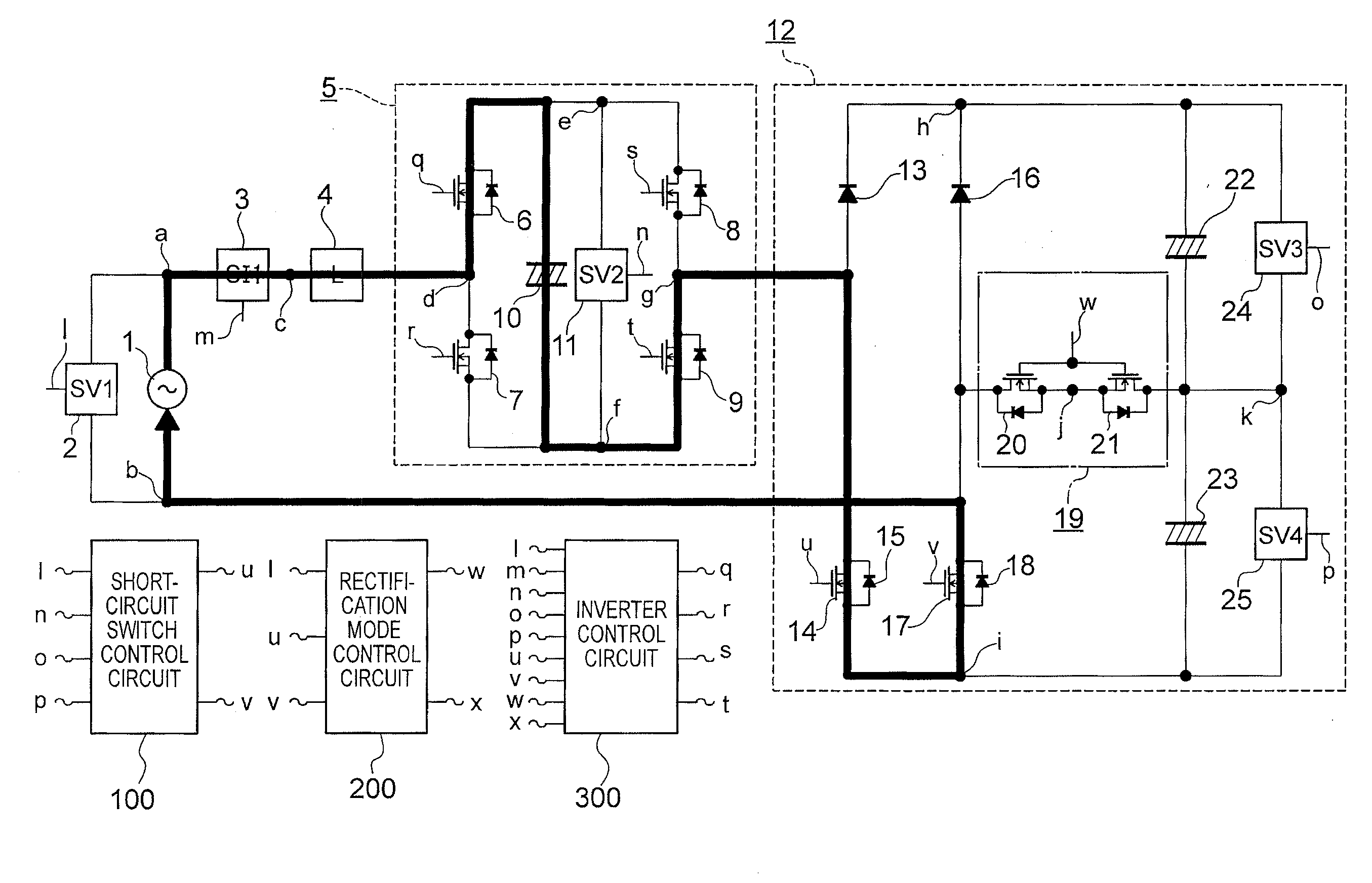
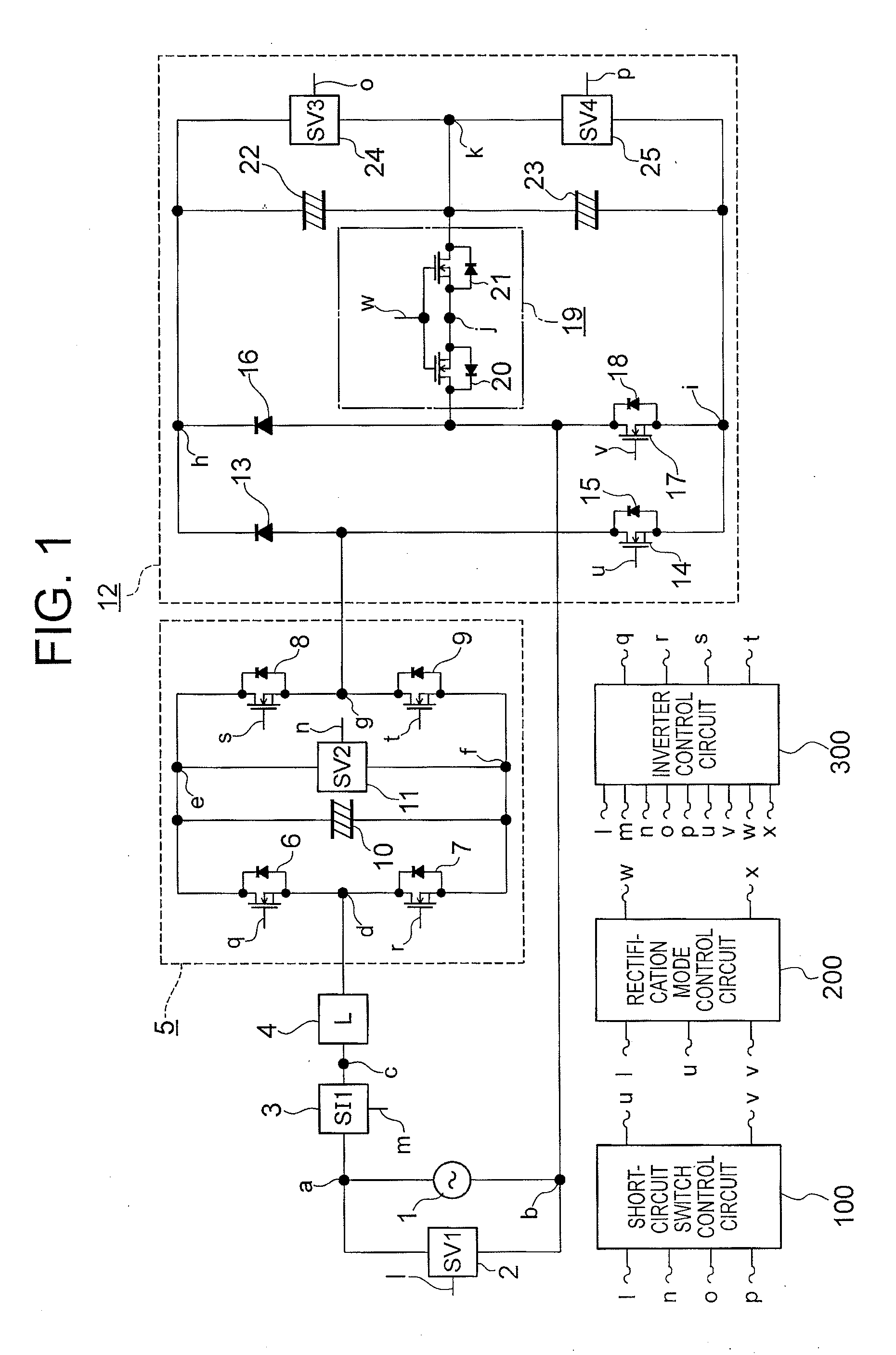
[0040]A power converter according to a first embodiment of the present invention is described with reference to FIGS. 1 to 23 and 27. FIG. 1 is a circuit diagram illustrating a structure of the power converter according to the first embodiment of the present invention. Hereinafter, the same reference symbols in the respective drawings indicate the same or corresponding portions.

[0041]In FIG. 1, the power converter according to the first embodiment of the present invention includes an AC input power supply 1 (hereinafter, simply referred to as AC power supply 1), a voltage detection circuit (SV1) 2, a current detection circuit (SI1) 3, a reactor (L) 4, an inverter circuit 5, a diode bridge full-wave rectifying circuit 12, a short-circuit switch control circuit 100, a rectification mode control circuit 200, and an inverter control circuit 300.

[0042]The AC power supply 1 is connected to the voltage detection circuit 2 and the current detection circuit 3 at a node “a”. The current detec...

second embodiment

[0123]A power converter according to a second embodiment of the present invention is described with reference to FIGS. 24 to 26. FIG. 24 is a circuit diagram illustrating a structure of the power converter according to the second embodiment of the present invention.

[0124]In FIG. 24, the power converter according to the second embodiment of the present invention includes an AC power supply 1, a voltage detection circuit (SV1) 2, a current detection circuit (SI1) 3, a reactor (L) 4, an inverter circuit 5, a short circuit 40, a diode bridge full-wave rectifying circuit 12A, a short-circuit switch control circuit 100, a rectification mode control circuit 200, and an inverter control circuit 300.

[0125]The short circuit 40 includes a short-circuit switch 14 and diodes 41, 42, 43, and 44.

[0126]The diodes 41 and 42 are connected in series at a node “g”. The diodes 43 and 44 are connected in series at a node “b”. One end of the short-circuit switch 14 including a semiconductor switch element...


PUM


Abstract

A power converter includes an inverter circuit for superimposing a generated voltage on an AC input voltage, a diode bridge full-wave rectifying circuit connected to the inverter circuit, smoothing capacitors connected between DC output terminals of the rectifying circuit, short-circuit switches connected to the rectifying circuit, a rectification mode changing circuit connected to the rectifying circuit, a short-circuit switch control circuit for maintaining the short-circuit switches in an on state in a short-circuit phase range, a rectification mode control circuit for maintaining the rectification mode changing circuit in an off state in the short-circuit phase range and an inverter control circuit for PWM-controlling the inverter circuit so that an output voltage of the rectifying circuit follows a target output voltage when the rectification mode changing circuit is in the off state.

Description

BACKGROUND OF THE INVENTION[0001]1. Field of the Invention[0002]The present invention relates to a power converter which includes an inverter circuit for improving an input power factor and converts AC power into DC power.[0003]2. Description of the Related Art[0004]In a conventional power converter, an inverter circuit (single-phase inverter) is connected in series to a rectifying circuit for rectifying an AC input in a subsequent stage of the rectifying circuit; and a smoothing capacitor is connected through a rectifying diode to the inverter circuit in a subsequent stage of the inverter circuit. Further, a short-circuit switch is provided to bypass the smoothing capacitor, and an output of the inverter circuit is controlled based on a current command so that a DC voltage of the smoothing capacitor follows a target voltage and an input power factor is improved (see, for example, JP 2009-095160 A).[0005]However, the conventional technology has the following problems. In the convent...

Claims


Application Information

Patent Timeline
Patent Type & Authority Applications(United States)
IPC IPC(8): H02J1/00
CPCH02M7/217
Inventor AWANE, KAZUTOSHIYAMADA, MASAKI
Owner MITSUBISHI ELECTRIC CORP
Why Eureka
Try Eureka