Wireless Power Transceiver and Wireless Power System

Active Publication Date: 2011-06-02
SAMSUNG ELECTRONICS CO LTD
View PDF5 Cites 88 Cited by
  • Summary
  • Abstract
  • Description
  • Claims
  • Application Information

AI Technical Summary

Benefits of technology

[0012]The coupling controller may control a frequency such that a reflected wave of a transmission signal transmitted from the tr

Problems solved by technology

Based on characteristics of a wireless environment, as the distance between a source resonator and a target reso

Method used


Image

  • Wireless Power Transceiver and Wireless Power System
  • Wireless Power Transceiver and Wireless Power System
  • Wireless Power Transceiver and Wireless Power System

Examples


Example

[0055]Throughout the drawings and the description, unless otherwise described, the same drawing reference numerals should be understood to refer to the same elements, features, and structures. The relative size and depiction of these elements may be exaggerated for clarity, illustration, and convenience.

DESCRIPTION

[0056]The following description is provided to assist the reader in gaining a comprehensive understanding of the methods, apparatuses, and / or systems described herein. Accordingly, various changes, modifications, and equivalents of the methods, apparatuses, and / or systems described herein may be suggested to those of ordinary skill in the art. Also, description of well-known functions and constructions may be omitted for increased clarity and conciseness.

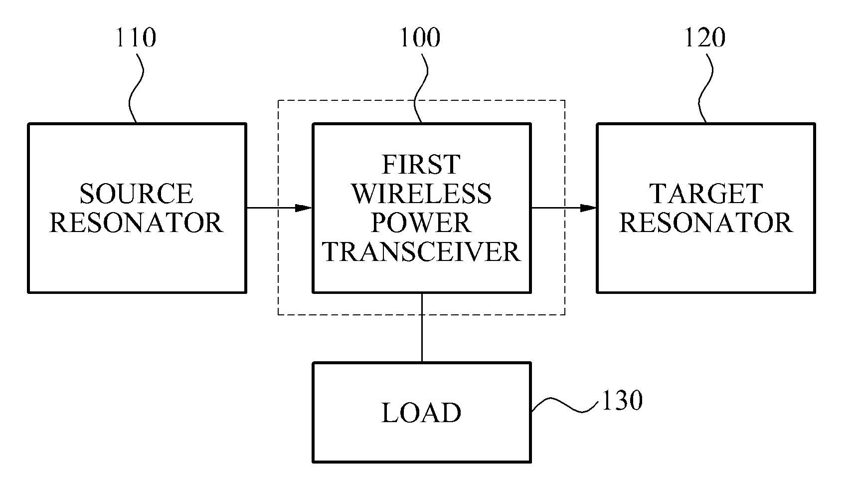
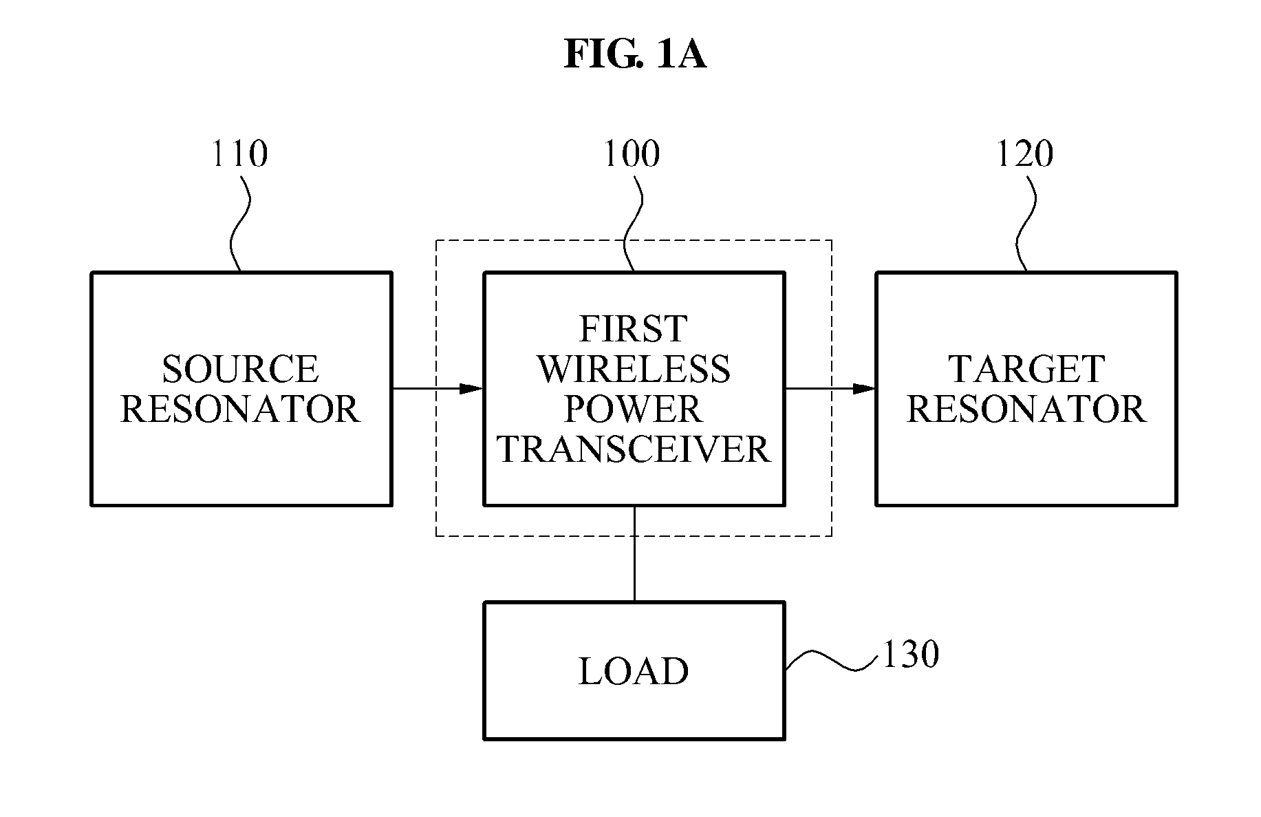
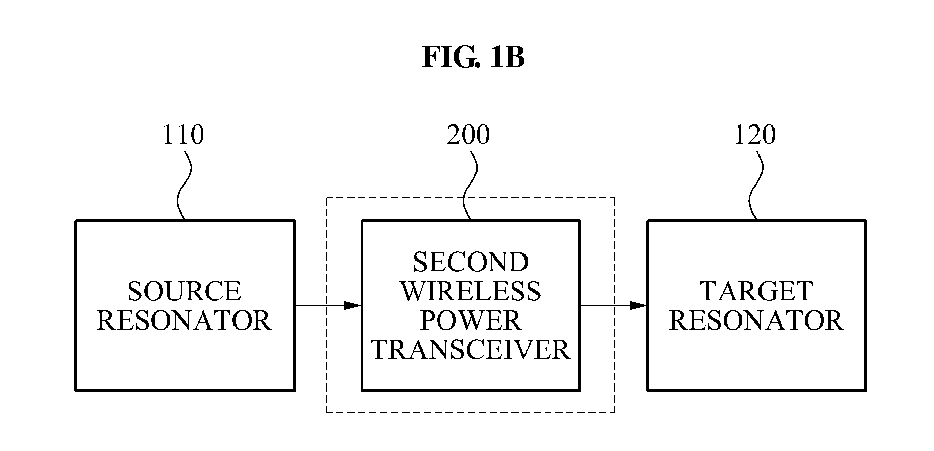
[0057]FIGS. 1A and 1B illustrate examples of wireless power systems. FIG. 1A includes a wireless power system that includes a first wireless power transceiver 100. FIG. 1B includes a wireless power system that includes a s...


PUM


Abstract

A wireless power transceiver that is disposed between a source resonator and a target resonator and that may increase wireless power transmission efficiency is provided. The wireless power transceiver may include a power receiver that includes a receiving resonator that receives an inbound power from a source resonator, a power transmitter that includes a transmitting resonator that transmits an outbound power to a target resonator, and a coupling controller to control a coupling frequency between the target resonator and the transmitting resonator.

Description

CROSS-REFERENCE TO RELATED APPLICATION(S)[0001]This application claims the benefit under 35 U.S.C. §119(a) of Korean Patent Application No. 10-2009-0116387, filed on Nov. 30, 2009, and Korean Patent Application No. 10-2010-0104370, filed on Oct. 26, 2010, in the Korean Intellectual Property Office, the entire disclosures of which are both incorporated herein by reference for all purposes.BACKGROUND[0002]1. Field[0003]The following description relates to a wireless power transceiver and a wireless power system, and more particularly, to a wireless power transceiver that may be disposed between a source resonator and a target resonator and that may improve wireless power transmission efficiency of a wireless power system.[0004]2. Description of Related Art[0005]With the development of Information Technology (IT), a variety of portable electronic devices and the amount of portable electronic devices have increased. One important aspect under consideration with portable electronic devic...

Claims


Application Information

Patent Timeline
IPC IPC(8): H01F38/14
CPCH02J5/005H02J50/12H02J50/50H02J50/90H04B5/0037
Inventor RYU, YOUNG HOPARK, EUN SEOKKWON, SANG WOOKHONG, YOUNG TACKKIM, NAM YUN
Owner SAMSUNG ELECTRONICS CO LTD
Why Eureka
Try Eureka