Charging apparatus for vehicle and method for charging vehicle

a charging apparatus and vehicle technology, applied in hybrid vehicles, secondary cells servicing/maintenance, electric devices, etc., can solve problems such as overheating of charging cables, and achieve the effect of suppressing the loss of charging opportunities and safely charging

Active Publication Date: 2011-06-02
TOYOTA JIDOSHA KK
View PDF7 Cites 56 Cited by
  • Summary
  • Abstract
  • Description
  • Claims
  • Application Information

AI Technical Summary

Benefits of technology

[0033]In the present invention, the electric power that can be supplied to the vehicle from the power supply external to the vehicle is detected, and if it is determined that the suppliable electric power is included in the predefined standard, charging is executed in accordance with the suppliable electric power. On the other hand, if it is determined that the suppliable electric power is not included in the predefined standard and if it is determined that the power supply is normal based on the voltage of the power supply external to the vehicle, charging is executed by limiting the charging current to the predefined value. If it is determined that the suppliable electric power is not included in the predefined standard and if it is determined that the power supply external to the vehicle is abnormal, charging is prohibited. In other words, if it is determined that the suppliable electric power is not included in the predefined standard, charging is not prohibited without exception, but executed by limiting the charging current if it is determined that the power supply external to the vehicle is normal.
[0034]Therefore, according to the present invention, loss of an opportunity for charging can be suppressed as much as possible, and the power storage device can be safely charged from the power supply external to the vehicle.

Problems solved by technology

When a charging current flowing from the power supply to the power storage device exceeds the rated current of the EVSE, there arise problems such as tripping of a breaker and overheating of the charging cable.

Method used


Image

  • Charging apparatus for vehicle and method for charging vehicle
  • Charging apparatus for vehicle and method for charging vehicle
  • Charging apparatus for vehicle and method for charging vehicle

Examples


Embodiment Construction

[0051]Embodiments of the present invention will be hereinafter described in detail with reference to the drawings. The same or corresponding portions are represented by the same reference characters in the drawings, and description thereof will not be repeated.

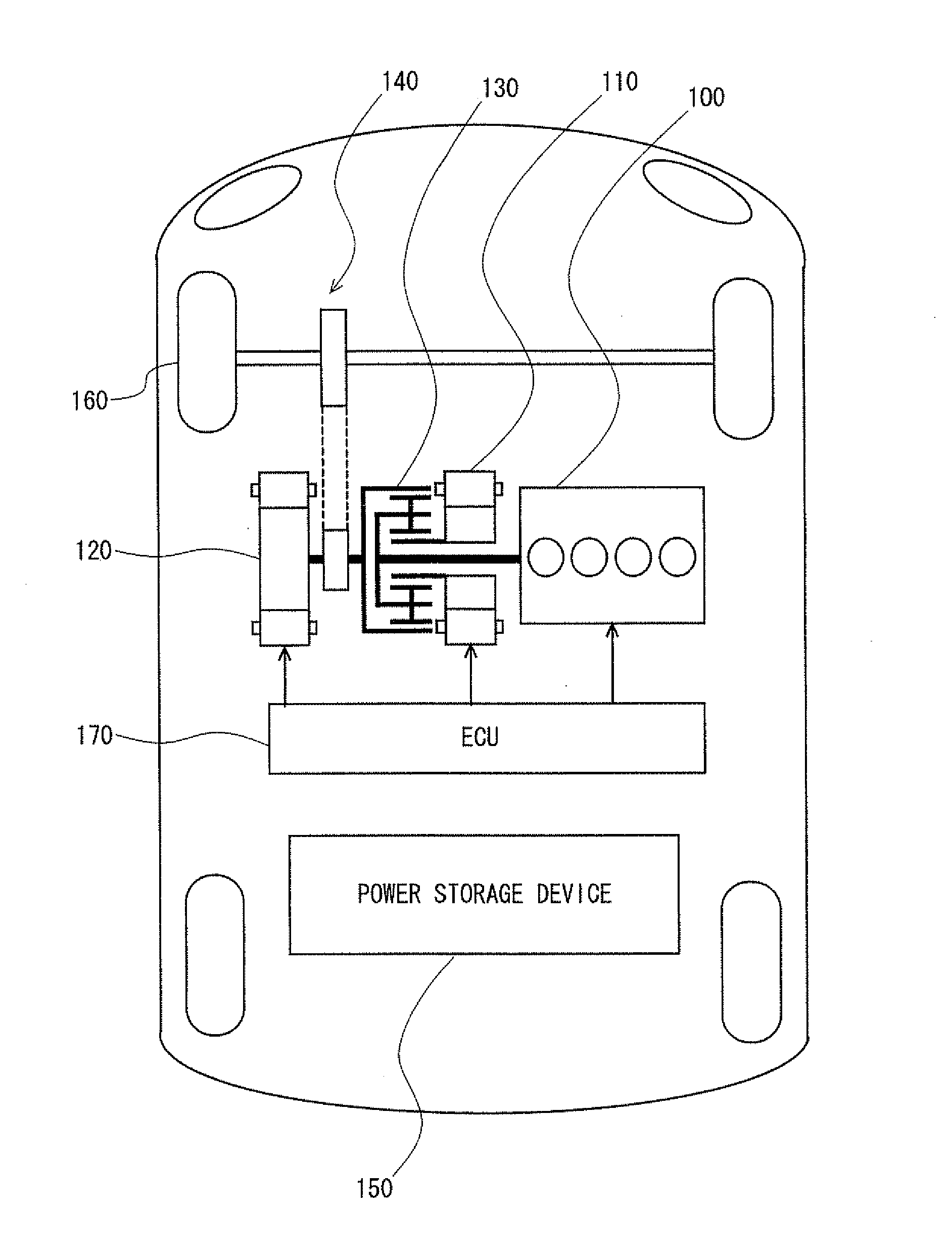
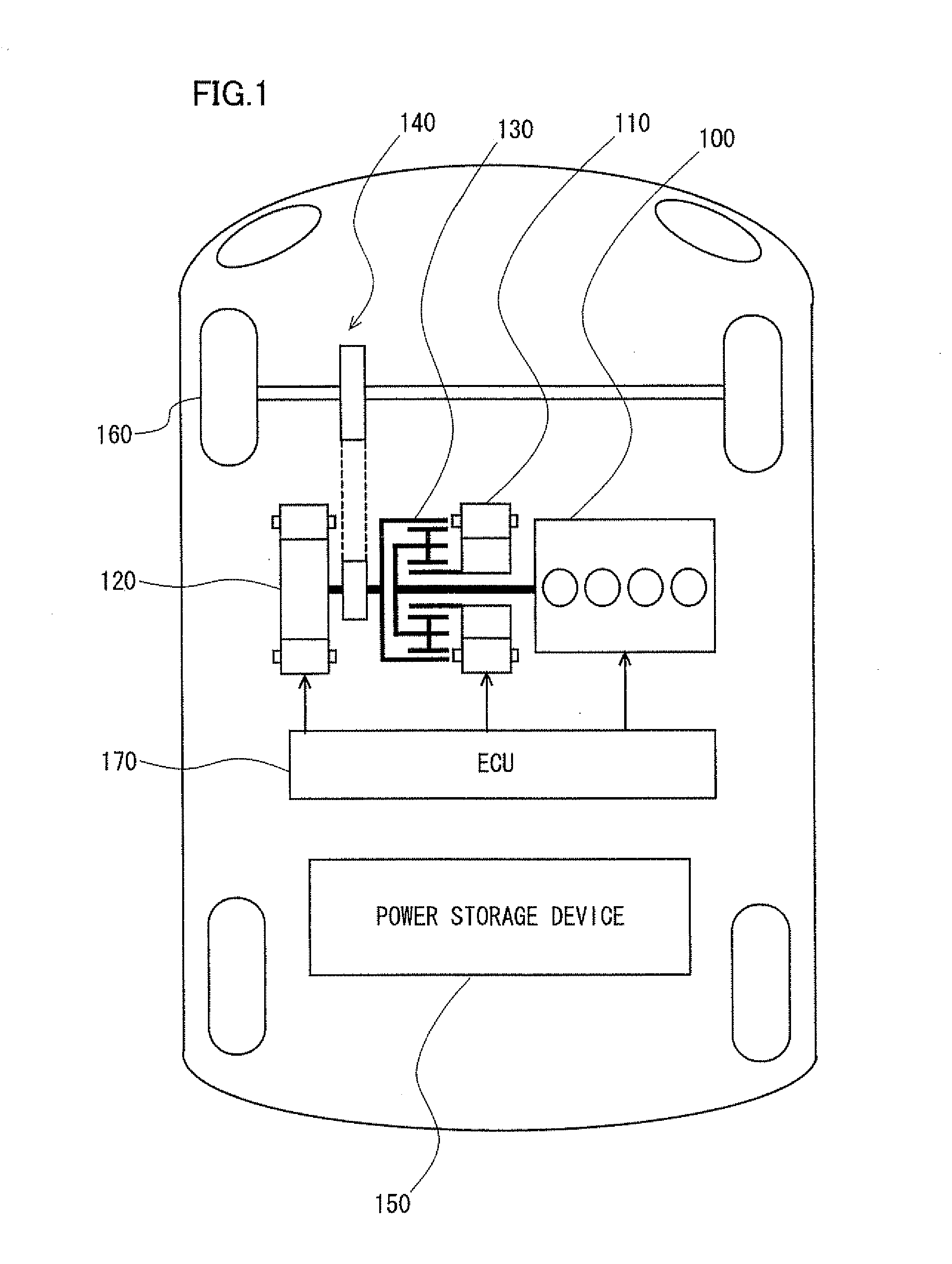
[0052]FIG. 1 is an overall block diagram of a plug-in hybrid vehicle shown as an example of a vehicle on which a charging apparatus for a vehicle according to an embodiment of the present invention is mounted. Referring to FIG. 1, this plug-in hybrid vehicle includes an engine 100, a first MG (Motor Generator) 110, a second MG 120, a power split device 130, a reduction gear 140, a power storage device 150, a drive wheel 160, and an ECU (Electronic Control Unit) 170.

[0053]Engine 100, first MG 110 and second MG 120 are coupled to power split device 130. This plug-in hybrid vehicle travels by using driving force from at least one of engine 100 and second MG 120. Motive power generated by engine 100 is split by power split device ...


PUM


Abstract

An ECU detects a rated current that can be supplied from a power supply to a power storage device, based on a pilot signal. If a combination of detected values of a voltage; the rated current and a power supply frequency matches a predefined combination, the ECU executes charging with a voltage, a current and a frequency in accordance with the combination. On the other hand, if it is determined that the combination of the voltage, the rated current and the frequency does not match any one of predefined combinations and if it is determined that the power supply itself is normal, the ECU executes charging by limiting a charging current to a predefined minimum rated current value. If it is determined that the combination of the voltage, the rated current and the frequency does not match any one of predefined combinations and if it is determined that the power supply is abnormal, the ECU prohibits charging.

Description

TECHNICAL FIELD[0001]The present invention relates to a charging apparatus for a vehicle and a method for charging a vehicle. In particular, the present invention relates to a charging apparatus for a vehicle by which a vehicle-mounted power storage device for driving the vehicle is charged from a power supply external to the vehicle, and a method for charging the vehicle.BACKGROUND ART[0002]In recent years, an electric vehicle, a hybrid vehicle, a fuel cell vehicle and the like have received attention as an environmentally-friendly vehicle. On these vehicles, a motor that generates driving force for traveling as well as a power storage device that stores electric power supplied to the motor are mounted. The hybrid vehicle further has an internal combustion engine mounted thereon as a power source, together with the motor. The fuel cell vehicle has a fuel cell mounted thereon as a direct current (DC) power supply for driving the vehicle.[0003]Among these vehicles, a vehicle is known...

Claims


Application Information

Patent Timeline
Patent Type & Authority Applications(United States)
IPC IPC(8): H02J7/00
CPCB60K1/02Y02T90/14B60K6/445B60L11/1812B60L11/1814B60L11/1816B60L2220/14B60L2220/54B60L2230/12B60W10/08B60W10/26B60W20/00B60W2510/244H01M10/44Y02T10/6239Y02T10/6269Y02T10/641Y02T10/7005Y02T10/7088Y02T90/121Y02T90/127B60K6/365B60L53/14B60L53/22B60L53/24B60L53/18Y02T10/62Y02T10/64Y02T10/7072Y02T10/70Y02E60/10B60W10/24B60W2710/24B60W2510/24B60W20/13Y02T90/12
Inventor MITSUTANI, NORITAKE
Owner TOYOTA JIDOSHA KK
Why Eureka
Try Eureka