
Microdischarge-based pressure sensor and method

a pressure sensor and micro-discharge technology, applied in the field of pressure sensors and mems devices, can solve the problems of measurable interference changes in reflected light, micro-discharge-based pressure sensors are fundamentally different from ion gauges, and cannot be conventionally measured in discharge-based devices

Active Publication Date: 2011-06-02
RGT UNIV OF MICHIGAN
View PDF5 Cites 17 Cited by
  • Summary
  • Abstract
  • Description
  • Claims
  • Application Information

AI Technical Summary

Problems solved by technology

Typically, these use an optically reflective cavity on the end of a fiber optic cable; the cavity size changes with pressure, causing measurable interference changes in reflected light.
Additionally, pressures within this range have not been conventionally measured by technologies involving discharges-based devices.
Microdischarge-based pressure sensors are fundamentally different than ion gauges, which are not effective at atmospheric pressure because the small mean free path of the created ions, 20-65 nm, makes them difficult to detect at the collector.

Method used


Image

  • Microdischarge-based pressure sensor and method
  • Microdischarge-based pressure sensor and method
  • Microdischarge-based pressure sensor and method

Examples


first embodiment

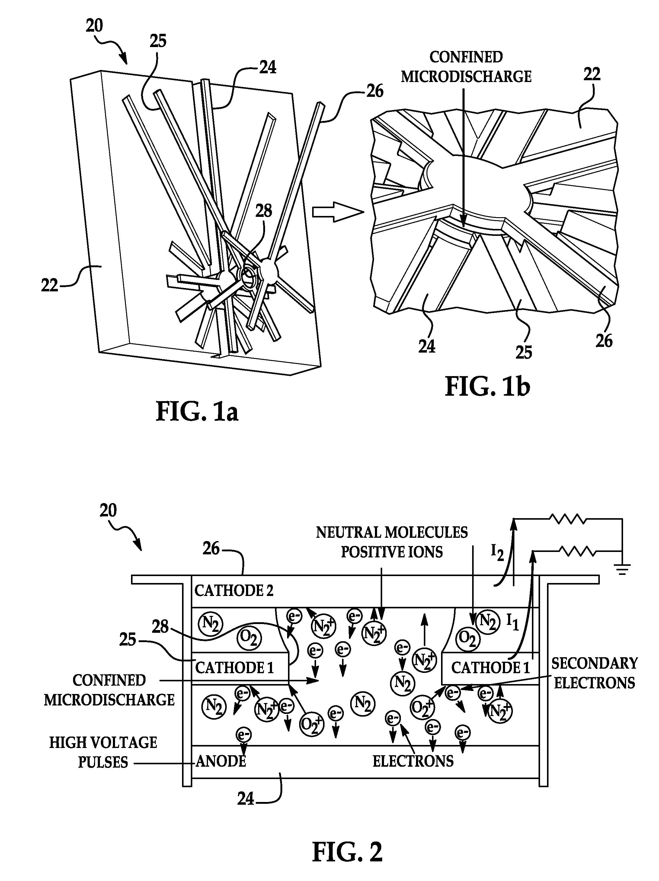
[0035]FIG. 1 depicts the main components of a microdischarge pressure sensor 20 that includes a quartz chip substrate 22 and three electrodes including an anode 24, a first, middle cathode 25, and a second, upper cathode 26. These electrodes 24-26 are suspended over a cavity in the quartz chip 22. The quartz chip is a monolithic substrate that supports each of the electrodes at a desired spacing relative to the other electrodes. Each electrode 24-26 has a single lead for electrical contact and between one and three additional supports, which maintain the suspended position of the electrode. A microdischarge chamber exists in the center of the chip, in a through-hole, as shown in FIG. 1. The single anode electrode 24 is disk-shaped and serves as the bottom of the chamber while the center electrode 25 is annular, or torus-shaped, thereby having a central opening 28 that allows the discharges to exist between the bottom anode 24 and both cathodes 25, 26. The top cathode 26 is disk-shap...


PUM


Abstract

A microdischarge-based pressure sensor that includes an anode, two cathodes, a drive circuit connected to the electrodes, and a measurement circuit that permits sensing of transient current pulses flowing through at least one of the electrodes. One of the cathodes is interposed between the anode and other cathode, and it includes a central opening which permits a microdischarge to occur between the anode and each cathode in response to applied voltage pulses from the drive circuit. Changes in relative current between the two cathodes are indicative of changes in ambient pressure in the microdischarge chamber. In other embodiments, a sealed chamber can be used with one of the electrodes acting as a diaphragm which deflects based on external pressure and changes its inter-electrode spacing, thereby altering the relative cathode currents.

Description

CROSS-REFERENCE TO RELATED APPLICATION[0001]This application claims the benefit of U.S. Provisional Application No. 61 / 183,056, filed Jun. 1, 2009, the entire contents of which are hereby incorporated by reference.[0002]This invention was made with government support under grants EEC0233187, EC9986866, and ECS0734962 awarded by the National Science Foundation. The government has certain rights in the invention.TECHNICAL FIELD[0003]This invention relates generally to pressure sensors and MEMS devices and, more particularly, to techniques and devices for measuring pressure in high-temperature environments using microdischarge plasmas.BACKGROUND OF THE INVENTION[0004]Pressure sensors that can operate at high temperatures have uses in numerous industrial sectors, and have been used in gas turbine engines, coal boilers, furnaces, and machinery for oil / gas exploration. A number of optical approaches have been reported in the past, utilizing Fabry-Perot and other interferometers. Typically...

Claims


Application Information

Patent Timeline
IPC IPC(8): G01L21/30
CPCG01L9/0072
Inventor GIANCHANDANI, YOGESHWRIGHT, SCOTT
Owner RGT UNIV OF MICHIGAN
Learn More