
Communication device and method of communication that provide a silent period for detection and avoidance

Inactive Publication Date: 2011-06-02
KONINKLIJKE PHILIPS ELECTRONICS NV
View PDF4 Cites 9 Cited by
  • Summary
  • Abstract
  • Description
  • Claims
  • Application Information

AI Technical Summary

Benefits of technology

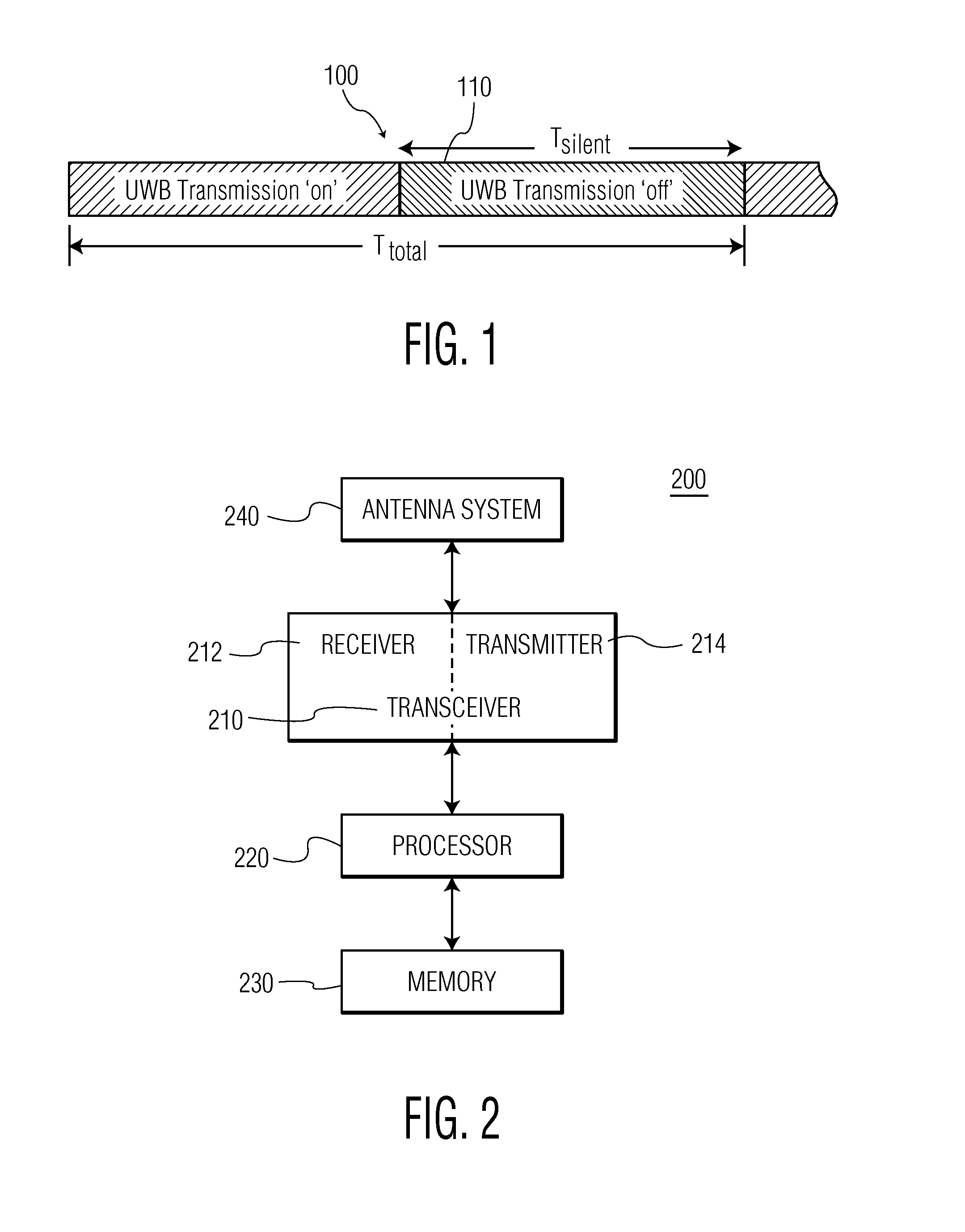
[0008]FIG. 1 illustrates silent periods in a UWB transmission. FIG. 1 illustrates how in each time period 100, TTOTAL, all UWB devices must remain silent for a time interval 110, TSILENT. Experiments have shown that to minimize the impact of UWB wireless devices on WiMAX subscriber units, and to insure that the WiMAX subscriber units will be able to “hear” a downlink signal from a WiMAX base station and then transmit an uplink signal which can be detected by nearby UWB wireless devices, TSILENT should be about 250˜300 ms and TTOTAL should be about 900 ms.

Problems solved by technology

As the demand for new wireless communication services and systems continues to expand, appropriate unused frequency spectrum for these new wireless systems becomes more difficult to identify.
Meanwhile, in many situations it is the case that spectrum that has been previously allocated to existing services and systems actually is unused for extending periods of time in some geographical areas.
In particular, incumbent wireless devices that operate according to the emerging, worldwide WiMAX communication protocol may be affected by interference from UWB wireless devices.
If a WiMAX subscriber unit is located near one or more UWB wireless devices with heavy data traffic, and / or on the fringe of the coverage area of a WiMAX base station, then the WiMAX subscriber unit may not be able to receive the WiMAX base station's signal.
Without an uplink transmission from the WiMAX subscriber unit, any nearby UWB wireless devices will not be able to detect the WiMax subscriber to avoid interfering with it.
So this becomes a circular problem.
Unfortunately, a silent period of 250˜300 ms has a severe, negative, impact on the operation of UWB wireless devices.
In addition, the data transmission also has to be suspended during the silent period, which can easily compromise quality of service (QoS) requirements for some UWB applications.

Method used


Image

  • Communication device and method of communication that provide a silent period for detection and avoidance
  • Communication device and method of communication that provide a silent period for detection and avoidance
  • Communication device and method of communication that provide a silent period for detection and avoidance

Examples


Embodiment Construction

[0019]FIG. 2 is a functional block diagram of a wireless device 100. As will be appreciated by those skilled in the art, one or more of the various “parts” shown in FIG. 2 may be physically implemented using a software-controlled microprocessor, hard-wired logic circuits, or a combination thereof. Also, while the parts are functionally segregated in FIG. 2 for explanation purposes, they may be combined variously in any physical implementation.

[0020]Wireless device 200 includes a transceiver 210, processor 220, memory 230, and an antenna system 240.

[0021]Transceiver 210 includes a receiver 212 and a transmitter 214 and provides functionality for wireless device 200 to communicate with other wireless devices in a wireless communication network according to the standard protocols of the wireless communication network. For example, in one embodiment wireless device 200 is a UWB wireless device adapted to operate using a communication protocol according to the WiMedia specifications.

[002...


PUM


Abstract

A system and method (600) of communication by a wireless device (200) operating according to a first communication protocol in at least a first set of frequency bands (320), provides a silent period for detecting the presence of a second wireless device operating according to a second communication protocol in a second set of frequency bands (310) that at least partially overlaps the first set of frequency bands (320).

Description

CROSS-REFERENCES TO RELATED APPLICATIONS[0001]This patent application claims the priority benefit under 35 U.S.C. §119(e) of U.S. Provisional Patent Application 60 / 869,619, filed on 12 Dec. 2006, the entirety of which is hereby incorporated by reference as if fully set forth herein.TECHNICAL FIELD[0002]This invention pertains to the field of wireless communications, and more particularly to a wireless communication device and method of wireless communication in a communication network that provides a silent period for detecting the presence of other wireless communication devices operating in other wireless systems, to avoid interference with them.BACKGROUND AND SUMMARY[0003]As the demand for new wireless communication services and systems continues to expand, appropriate unused frequency spectrum for these new wireless systems becomes more difficult to identify. Meanwhile, in many situations it is the case that spectrum that has been previously allocated to existing services and sy...

Claims


Application Information

Patent Timeline
IPC IPC(8): H04B1/69H04B1/713H04B1/7143
CPCH04B1/7143H04B1/71632H04B2001/7154H04L5/0007H04W72/1215H04L5/0058H04L27/0006H04W8/005H04W16/14H04L5/0037H04B1/7136
Inventor CHOU, CHUN-TING
Owner KONINKLIJKE PHILIPS ELECTRONICS NV
Learn More