FM detector, signal interpolation method, and related program

a detector and signal technology, applied in the field of fm detectors and signal interpolation methods, can solve problems such as significant signal distortion, and achieve the effect of reducing or minimizing the distortion of an fm-detection-result signal

Active Publication Date: 2011-06-02
JVC KENWOOD CORP A CORP OF JAPAN
View PDF6 Cites 9 Cited by
  • Summary
  • Abstract
  • Description
  • Claims
  • Application Information

AI Technical Summary

Benefits of technology

[0008]It is a first object of this invention to provide an FM detector which implements signal interpolation in response to the detection of a noise for a time as short as possible, and thereby minimizes a signal distortion caused by the implementation of the signal interpolation.
[0009]It is a second object of this invention to provide a method of implementing signal interpolation in response to the detection of a noise for a time as short as possible, and thereby minimizing a signal distortion caused by the implementation of the signal interpolation.
[0010]It is a third object of this invention to provide a computer program for implementing signal interpolation in FM detection in response to the detection of a noise for a time as short as possible, and thereby minimizing a signal distortion caused by the implementation of the signal interpolation.
[0021]This invention has the following advantages. It is possible to decide whether signal interpolation is necessary or unnecessary on the basis of noise. Furthermore, it is possible to reduce or minimizes a distortion of an FM-detection-result signal which is caused by noise.

Problems solved by technology

The signal interpolation of this type tends to cause a significant signal distortion.

Method used


Image

  • FM detector, signal interpolation method, and related program
  • FM detector, signal interpolation method, and related program
  • FM detector, signal interpolation method, and related program

Examples


Embodiment Construction

[0034]A prior-art device will be explained below for a better understanding of this invention.

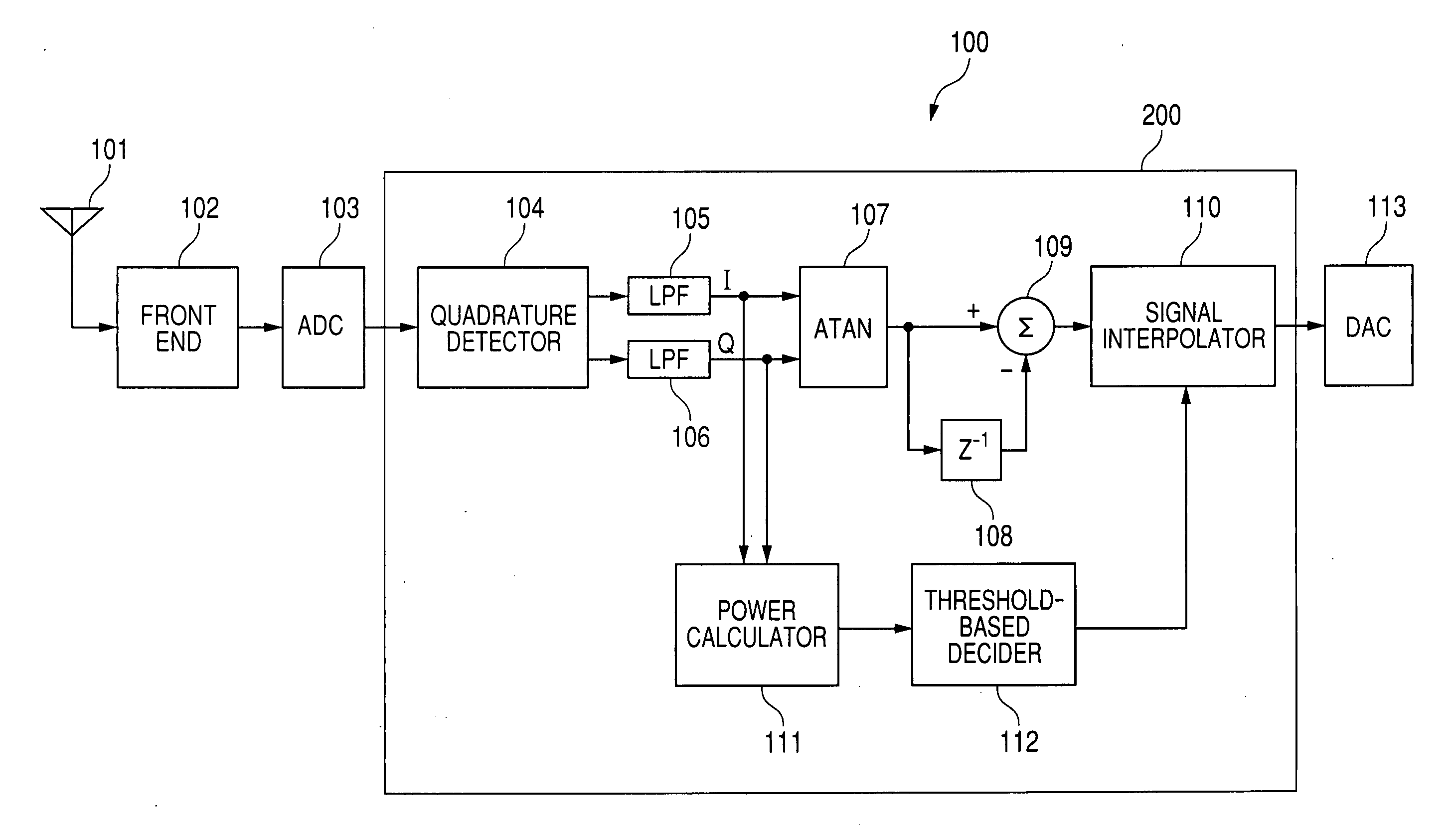
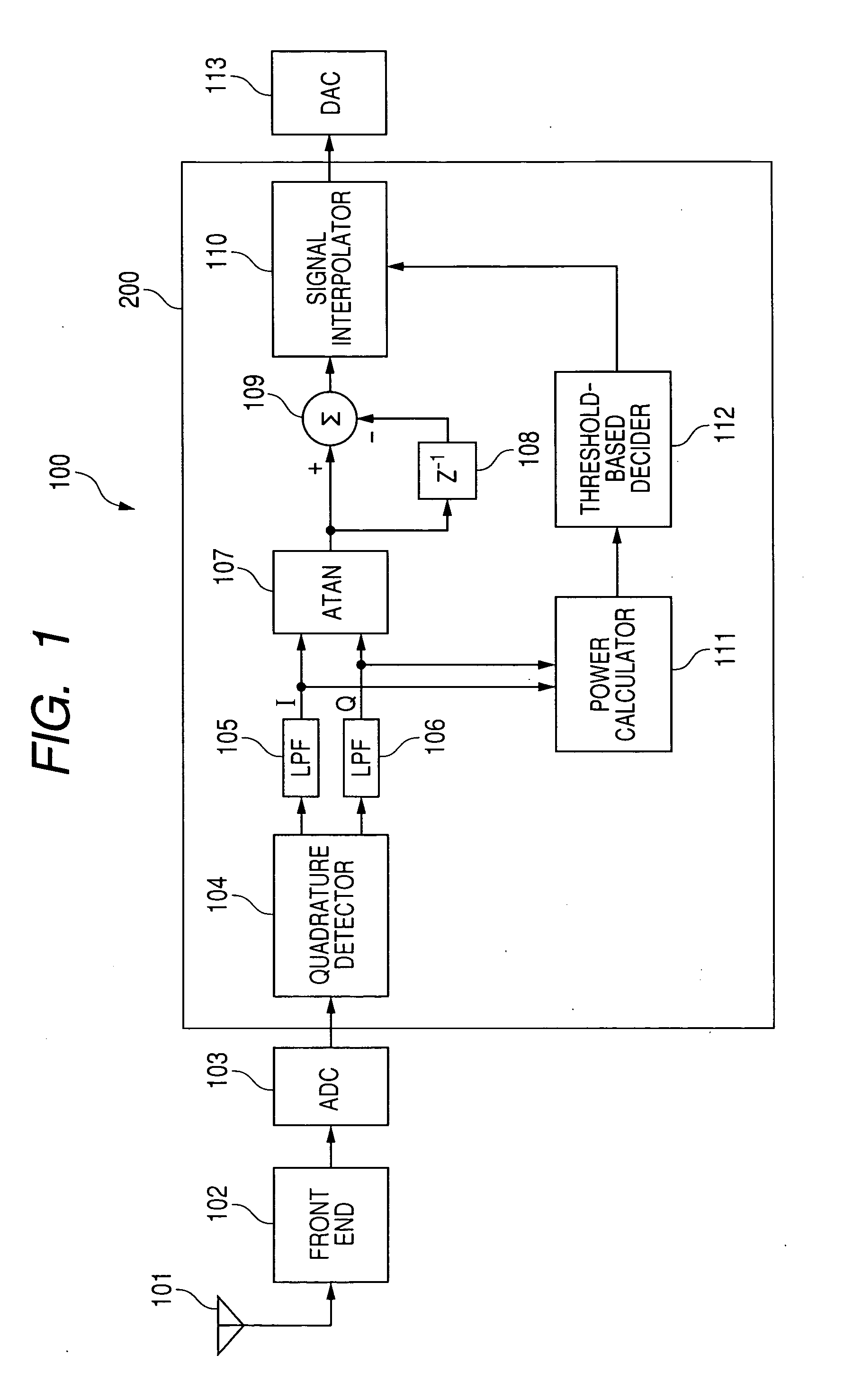
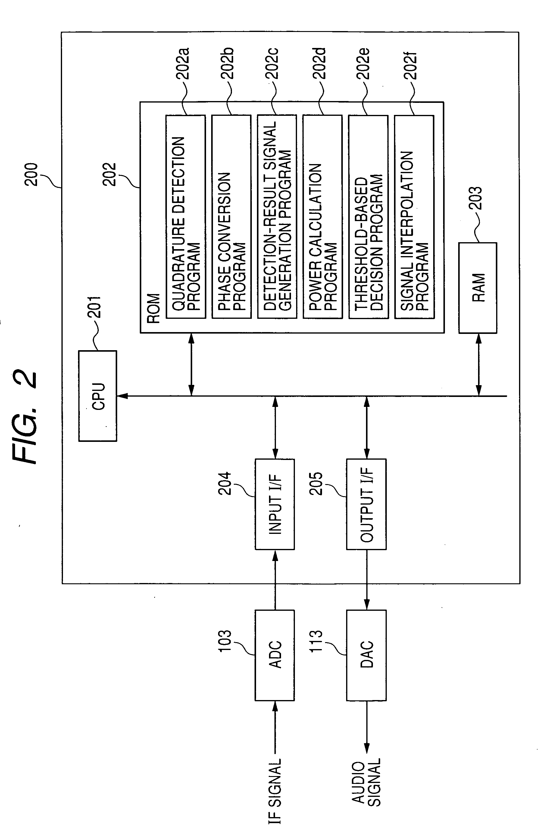
[0035]FIG. 12 shows a prior-art FM (frequency modulation) detector 500 disclosed in Japanese examined patent application publication number 6-71210.

[0036]In the prior-art FM detector 500, an FM-detection-result signal outputted from an FM detection circuit 1 is delayed by a delay circuit 2 including an LPF (a low pass filter). The delayed FM-detection-result signal is fed from the delay circuit 2 to a stereo demodulation circuit 5 via a gate circuit 3 and a level hold circuit 4.

[0037]The FM-detection-result signal is fed from the FM detection circuit 1 to an HPF (a high pass filter) 6. Noise-related signal components pass through the HPF 6 before being amplified by a noise amplifier 7. A full-wave rectification circuit 12 following the noise amplifier 7 makes the polarity of an output signal from the noise amplifier 7 into one direction.

[0038]The prior-art FM detector 500 includes an AM (am...


PUM


Abstract

A received FM wave signal is subjected to quadrature detection to generate baseband I and Q signals. The baseband I and Q signals are converted into a sequence of samples of phase information. An FM-detection-result signal is generated in response to a variation between two successive samples of the phase information. A power of the baseband I and Q signals is computed. A decision is made as to whether the baseband I and Q signals are valid or invalid by referring to the computed power and at least one threshold value. Signal interpolation is implemented with respect to the FM-detection-result signal in cases where it is decided that the baseband I and Q signals are invalid.

Description

BACKGROUND OF THE INVENTION[0001]1. Field of the Invention[0002]This invention relates to an FM detector, a signal interpolation method, and a computer program for the FM detector or the signal interpolation method.[0003]2. Description of the Related Art[0004]Japanese examined patent application publication number 6-71210 discloses a device for eliminating pulse noise in an FM receiver. In the device of Japanese publication number 6-71210, a front end converts an RF signal into an IF signal fed to an FM detection circuit and an AM detection circuit. The FM detection circuit is followed by an HPF-containing circuit for sensing the leading edge of every pulse noise in an output signal from the FM detection circuit, that is, the leading edge of every FM or PM pulse noise. The AM detection circuit is followed by an HPF-containing circuit for sensing the leading edge of every pulse noise in an output signal from the AM detection circuit, that is, the leading edge of every AM pulse noise....

Claims


Application Information

Patent Timeline
Patent Type & Authority Applications(United States)
IPC IPC(8): H04L27/00
CPCH04L27/1525
Inventor OKUHATA, YASUHIDE
Owner JVC KENWOOD CORP A CORP OF JAPAN
Why Eureka
Try Eureka