Support Leg and A Mobile Offshore Work Platform

Inactive Publication Date: 2011-06-02
SANY ELECTRIC CO LTD
View PDF4 Cites 13 Cited by
  • Summary
  • Abstract
  • Description
  • Claims
  • Application Information

AI Technical Summary

Benefits of technology

[0015]Compared with the prior art, the support leg for mobile offshore work platforms which is provided by the present invention, in addition to the support arm extending in a vertical direction, further comprises the support platform fixed to the lower end of the support arm, and the cross section area of the support platform is larger than that of the support arm; and as such, when wind turbine installations or other offshore works are carried out in predetermined sea areas of soft foundation ground, the support platform with relatively large cross section area thus is supported on a soft foundation ground by a larger area, so that a greater support force can be provided for the platform body, the stability of the mobile offshore work platform is improved, and the mobile offshore work platform can be used to complete wind turbine installations and other predetermined works in sea areas of soft foundation ground. At same time, since the support platform is located at the lower end of the support arm, the support arm may be made to have a smaller cross section area, the support leg thus remains to have a relatively light total weight.
[0016]In a further preferred technical solution of the support leg of the present invention, said support platform comprises a cavity having an opening located on the lower surface of the support platform. As such, when the support leg needs to be sunk to the sea floor and supported on the soft foundation ground, the cavity may be depressurized by using a filling and expelling pump, so that a negative pressure region will be created in the cavity, the air and water in the cavity are expelled out, the support platform of the support leg can be smoothly sunk into sea water, the particles of the soft foundation ground are flowed into the cavity, the support platform is deposited into the soft

Problems solved by technology

Generally speaking, each part of the wind turbine is heavy.
Because at present there is no large crane ship specifically designed to install a wind turbine, therefore, during the hoisting and mounting of a whole wind turbine, different hoisting and mounting processes need to be planned according to different wind turbines and different conditions of the predetermined sea area configurations, which makes the installation process very complicated.
Further, the cost for using or renting a large crane ship is quite high, which thus results in the expense increment of the installation of a wind turbine.
Furthermore, the large crane ship has the characteristic of a deeper draft, so that the large crane ship can not be used to perform the hoisting and mounting work in tidal flats and shallow sea areas, and the application of this manner is limited by the installation areas.
Although this solution can compensate for the defects existing in the former solution, there are also some problems in it.
In addition, when the support leg 200 is pulled out of the soft foundation ground 300, the friction force F2 will act on the support leg 200 in a reverse direction to make it difficult to pull t

Method used


Image

  • Support Leg and A Mobile Offshore Work Platform
  • Support Leg and A Mobile Offshore Work Platform
  • Support Leg and A Mobile Offshore Work Platform

Examples


first embodiment

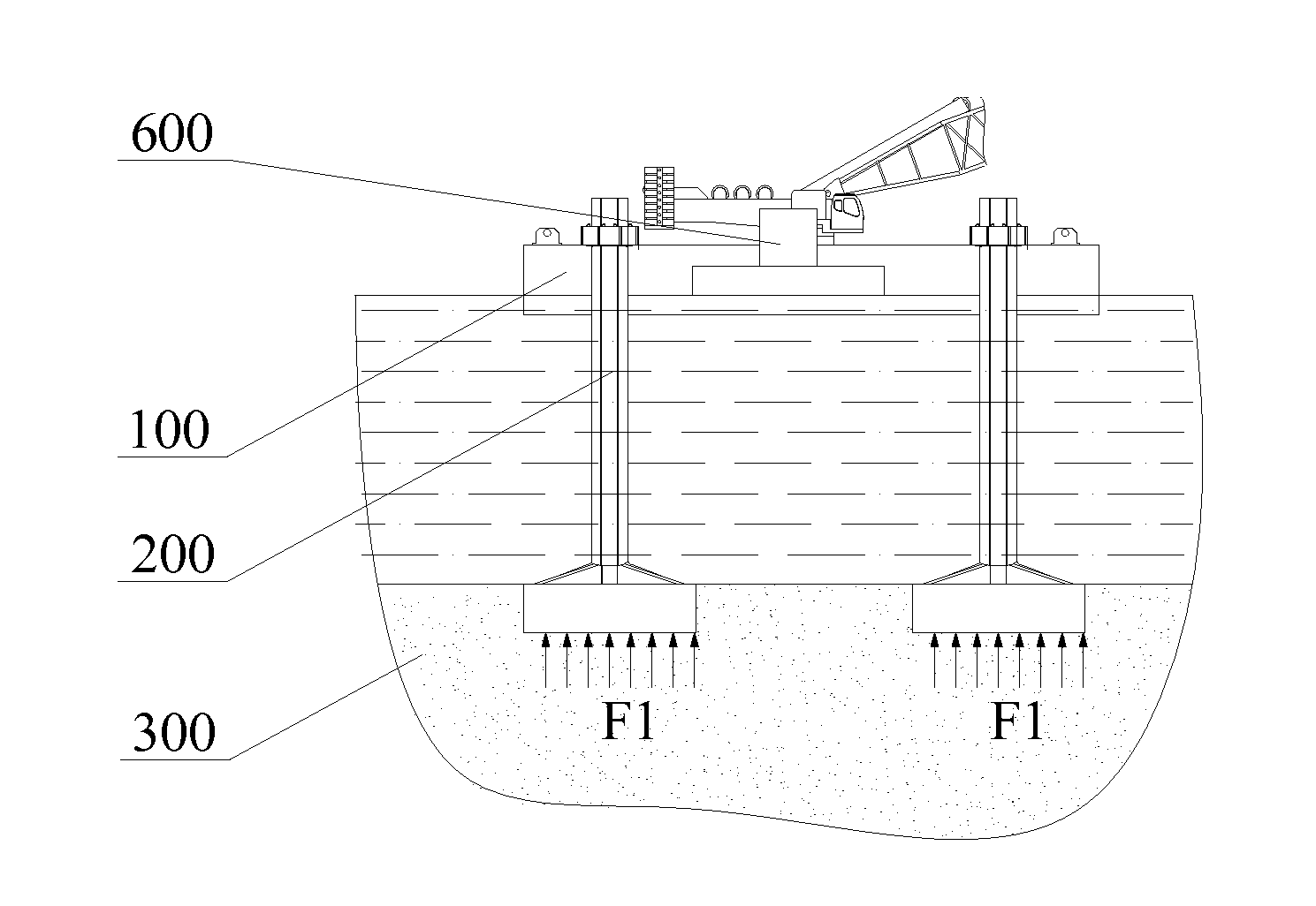
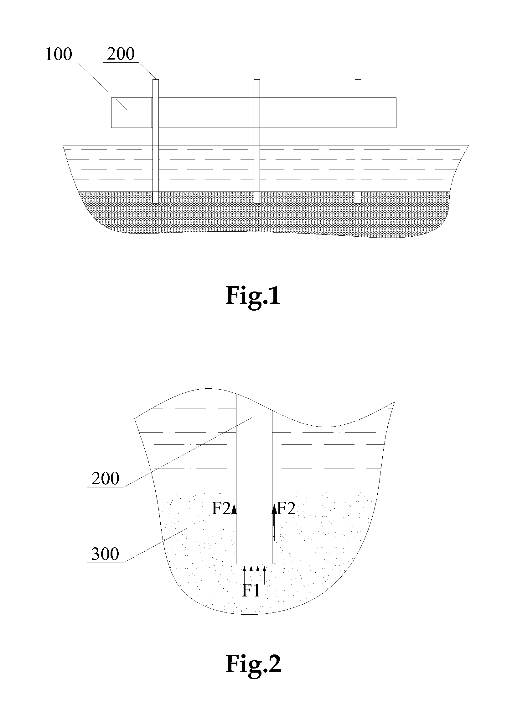
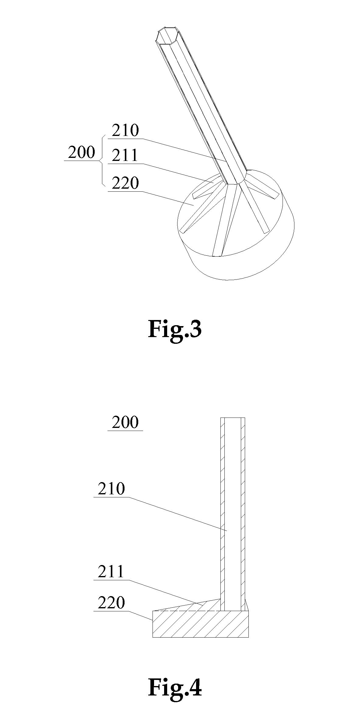
[0046]A support leg 200 according to support leg comprises a support arm 210 and a support platform 220. In this embodiment, the support arm 210 is formed by a hollow steel tube extending in a vertical direction, and the support platform 220 is a plate like body extending in a transversal direction and has a cross section larger than that of the support arm 210. A lower end of the support arm 210 is fixed to an upper surface of the support platform 220. For improving the reliability of fixation between them, between the side surface close to the lower end of the support arm 210 and the upper surface of the support platform 220 there is further provided a plurality of triangular reinforcing ribs 211, which have ends fixed to the side surface of the support arm 210 and bottom surfaces fixed to the support platform 220 and are disposed radially around and close to the lower end of the support arm 210. In addition, in order to facilitate the assembly of the support leg 200 with a platfo...

second embodiment

[0060]Please refer to FIG. 8, which is a schematic view of a structure of a support leg provided by the invention.

[0061]As compared with the support leg provided by the first embodiment of the support leg, one of differences of the support leg provided by the second embodiment is that the support platform 220 comprises a cavity 221 having an opening located on the bottom surface of the support platform 220.

[0062]The operation principle of the support leg 200 is as follows: when the support leg 200 needs to be sunk and supported on the sea floor foundation ground, by using a suitable filling and expelling pump to depressurize the cavity, the air and water in the cavity 221 are evacuated, a negative pressure is created inside the cavity 221, and the support leg is smoothly sunk and deposited on the sea floor foundation ground to provide a support force for the platform body 100; and after the predetermined offshore work has been finished, when the support leg 200 needs to be detached ...

third embodiment

[0065]It can be understood that the purpose of the pressure increment and reduction of the cavity 221 can be realized as long as the external port of the filling and expelling passage 222 is located on the outer surface of the support platforms 220 and the internal port thereof is located at the wall of the cavity 221. Therefore, the external port of the filling and expelling passage 222 may also be located on the other portions of the outer surface of the support platforms 220; as shown in FIG. 9, which is a schematic view of a structure of a support leg according to support leg according to the invention, at this time, the external port of the filling and expelling passage 222 is located between reinforcing ribs 211 on the upper surface of the support platforms 220, and as such, the filling and expelling passage 222 may also be connected with the filling and expelling pump provided on the platform body 100 through a delivery pipe 230; and in a case that predetermined conditions ar...


PUM


Abstract

The present invention discloses a support leg and a mobile offshore work platform having that leg. The disclosed support leg for a mobile offshore work platform comprises a support arm extending in a vertical direction, further comprising a support platform that has a cross section larger than that of the support arm, and that the lower end of said support arm is fixed to the upper surface of the support platform. When wind turbine installations or other offshore works are carried in sea areas of soft foundation ground, the support platform is supported on a soft foundation ground by a larger cross-sectional area, providing a greater support force and improving the stability of the mobile offshore work platform, and the mobile offshore work platform can be used to complete wind turbine installations and other predetermined works in sea areas of soft foundation ground.

Description

CROSS REFERENCE TO RELATED APPLICATIONS[0001]The application claims the benefit of Chinese Patent Application Nos. 200910237987.8, filed Nov. 27, 2009 and 201010112156.0, filed Feb. 10, 2010 under 35 U.S.C §§119(a)-(d), which are hereby incorporated by reference in their entirety.TECHNICAL FIELD[0002]This invention relates to an offshore work platform technology, and particularly, to a support leg for a mobile offshore work platform and a mobile offshore work platform having the support leg.BACKGROUND ART[0003]Offshore wind power generation technology concerns transformation of wind energy into electrical energy by means of one or more wind turbines installed in a wind farm located in an appropriate sea area. A wind turbine generally comprises a tower, a wind rotor and a nacelle, wherein the nacelle is provided with a generator, a gearbox and a main shaft. The bottom of the tower is installed to the wind turbine foundation of the wind farm, and the wind rotor and the nacelle are ins...

Claims


Application Information

Patent Timeline
IPC IPC(8): E02D5/74
CPCB63B21/26E02B17/021Y02E10/722E02B2017/0078E02D27/52E02B2017/0056Y02E10/72
Inventor WU, JIALIANGWANG, XINMINGLI, YANLINBAI, JUNLEI
Owner SANY ELECTRIC CO LTD
Why Eureka
Try Eureka