Vibration logging in computers

Inactive Publication Date: 2011-06-02
SAFE INNOVATIONS
View PDF9 Cites 19 Cited by
  • Summary
  • Abstract
  • Description
  • Claims
  • Application Information

AI Technical Summary

Problems solved by technology
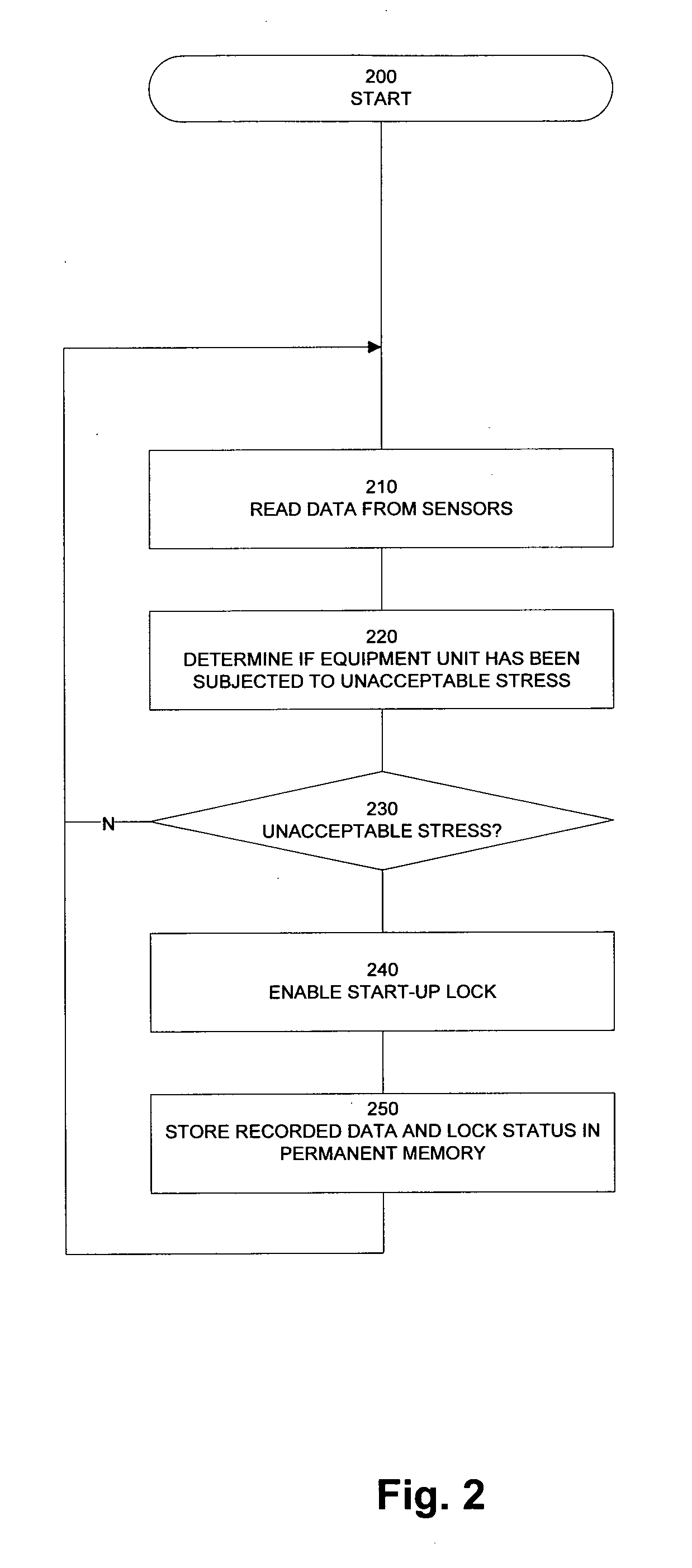
However, it cannot be seen that this previously known solution involves the prevention of possibly damaged equipment from being started up.

Method used


Image

  • Vibration logging in computers
  • Vibration logging in computers
  • Vibration logging in computers

Examples


Embodiment Construction

[0019]Detailed reference is now made to the present invention, examples of which are illustrated in the attached drawings. Wherever possible, the same reference numerals will be used throughout the drawings to refer to the same or like parts.

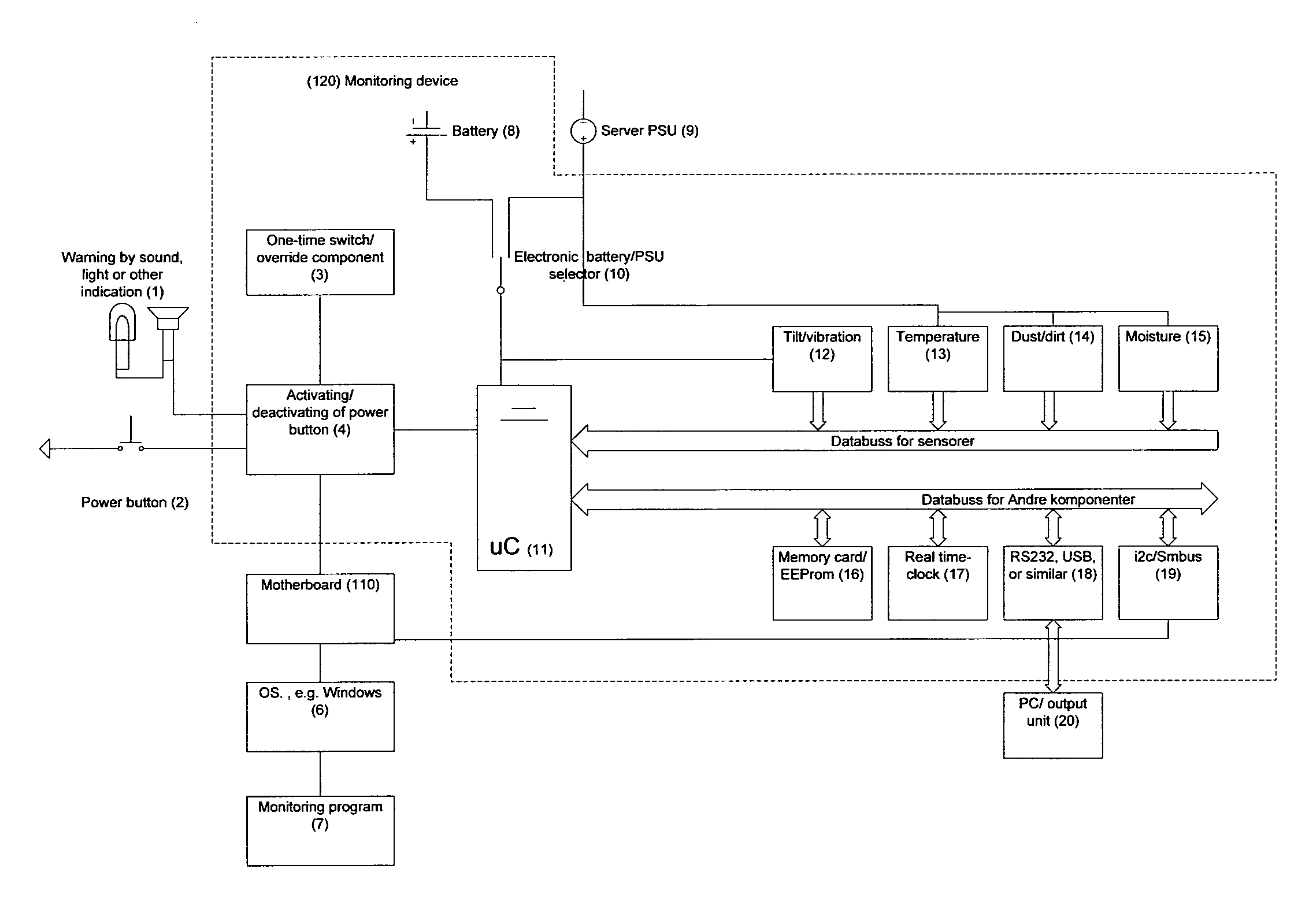
[0020]FIG. 1 is an exemplary block diagram illustrating general principles of an equipment unit provided with a monitoring device in accordance with the invention.

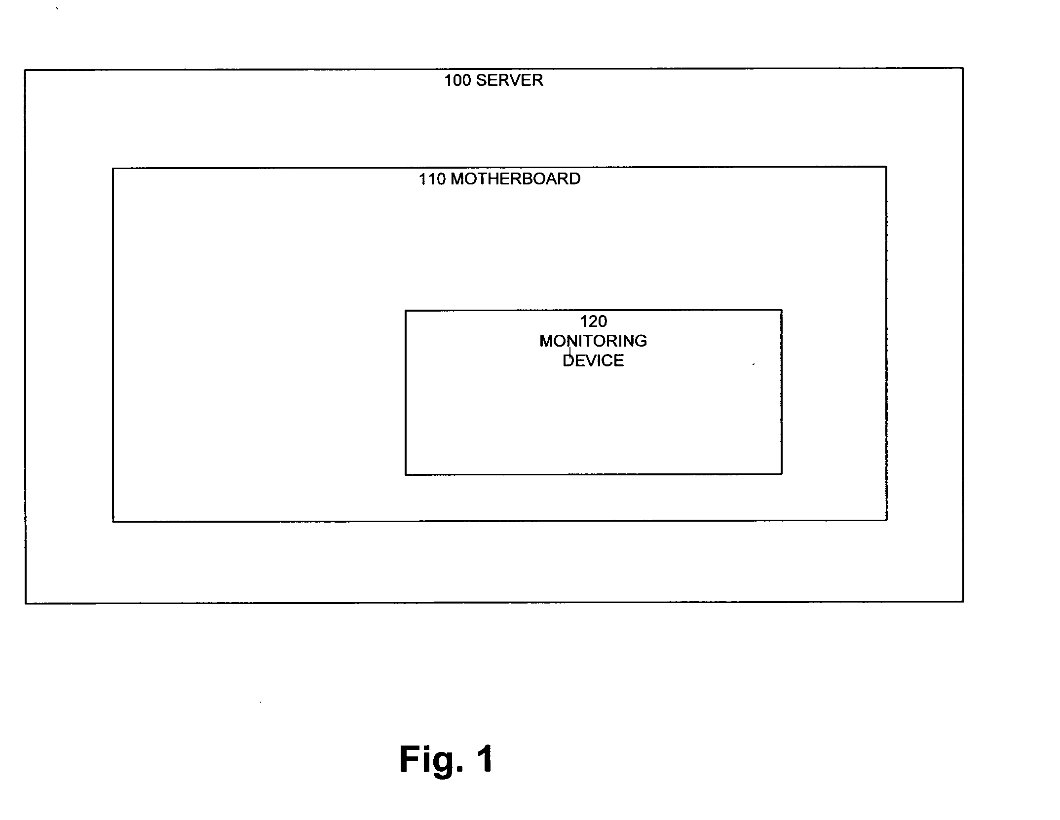
[0021]The equipment unit 100 may, in one example, be a computer such as a server. Alternatively, the equipment unit may be a computer of another type, e.g. a work station, a personal computer, in particular of the stationary type, or, as an alternative, of the portable type. Alternatively, the equipment unit may be other electronic equipment, such as a network element (a router, a switch, a bridge, a hub, a gateway, a firewall, a modem, or the like). Further alternatives include medical equipment, measuring equipment, automation equipment and so forth.

[0022]The equipment unit 100 compr...


PUM

PropertyMeasurementUnit
stressaaaaaaaaaa
poweraaaaaaaaaa
humidityaaaaaaaaaa

Abstract

The invention relates to a process and a monitoring device for monitoring an equipment unit, carried out by a processing device in the monitoring device. The process comprises reading at least one sensor signal and determining, on the basis of the at least one sensor signal, whether the equipment unit has been subjected to an unacceptable stress. If the equipment device has been subjected to an unacceptable stress, a start-up lock for the equipment unit is enabled, and lock status information is stored. The step of determining whether the equipment unit has been subjected to an unacceptable stress may comprise criteria that are dependent upon whether the monitoring device is operating in a low-power mode or a normal power mode. When a signal is received that indicates that the equipment unit is to be started up, it is determined whether the start-up lock has been enabled. If it has been enabled, a warning is activated. If, in addition, a non-reversible switch has not been activated, the warning is maintained and further operation of the equipment unit is prevented.

Description

FIELD OF THE INVENTION[0001]The present invention relates to the automatic monitoring of equipment such as computers.[0002]Specifically, the invention relates to a process for monitoring an equipment unit, a corresponding set of processing instructions, a corresponding monitoring device and an equipment unit comprising such a monitoring deviceBACKGROUND OF THE INVENTION[0003]There is a general need to monitor equipment, particularly electronic equipment such as computers, and especially servers, before and after the equipment has been put into operation.[0004]There is a particular need to monitor the equipment in a period from it leaving the manufacturer until a time during its operating phase, especially when the guarantee period has expired.[0005]Furthermore, there is a need to document that the equipment has been subjected to certain external events in different phases of this period, and there is a need to initiate measures as a consequence of the events that have taken place.[0...

Claims


Application Information

Patent Timeline
Patent Type & Authority Applications(United States)
IPC IPC(8): G01K1/00G06F19/00G01N5/02G01N21/59G01P15/00
CPCG01D3/08G01D9/005G08B21/187G07C3/08G05B19/0425
Inventor TUSVIK, OYSTEIN
Owner SAFE INNOVATIONS
Why Eureka
Try Eureka