Plasma processing apparatus

a processing apparatus and plasma technology, applied in the direction of coatings, chemical vapor deposition coatings, electric discharge tubes, etc., can solve the problems of affecting the miniaturization of the entire apparatus, affecting the miniaturization of the whole apparatus, and reducing the process uniformity of the wafer surface, so as to reduce the size of the apparatus, improve the process uniformity, and reduce the effect of unnecessary spa

Inactive Publication Date: 2011-06-09
TOKYO ELECTRON LTD
View PDF50 Cites 234 Cited by
  • Summary
  • Abstract
  • Description
  • Claims
  • Application Information

AI Technical Summary

Benefits of technology

[0010]In view of the foregoing, the present disclosure provides a plasma processing apparatus capable of improving process uniformity in wafer surface, and reducing the size of the apparatus by reducing unnecessary space within a processing chamber and also capable of easily varying a distance between an upper electrode and a lower electrode, as compared to conventional cases.
[0012]In accordance with the present disclosure, it is possible to provide the plasma processing apparatus capable of improving process uniformity in the wafer surface, and reducing the size of the apparatus by reducing unnecessary space within the processing chamber and also capable of easily varying the distance between the upper electrode and the lower electrode, as compared to conventional cases.

Problems solved by technology

Such a gas flow may cause a difference in processing states of the center and the periphery of the substrate, resulting in deterioration of process uniformity in the surface.
Thus, unnecessary space may increase, which may hinder miniaturization of the entire apparatus.
However, since the inside of a processing chamber is turned into a depressurized atmosphere, a great force is required for a driving mechanism to move the upper electrode (shower head) or the lower electrode (mounting table) up and down against a pressure difference between the inside and the outside of the processing chamber, and, thus, a great amount of energy is required for the driving.

Method used


Image

  • Plasma processing apparatus
  • Plasma processing apparatus
  • Plasma processing apparatus

Examples


Embodiment Construction

[0019]Hereinafter, embodiments of the present disclosure will be described in detail with reference to the accompanying drawings.

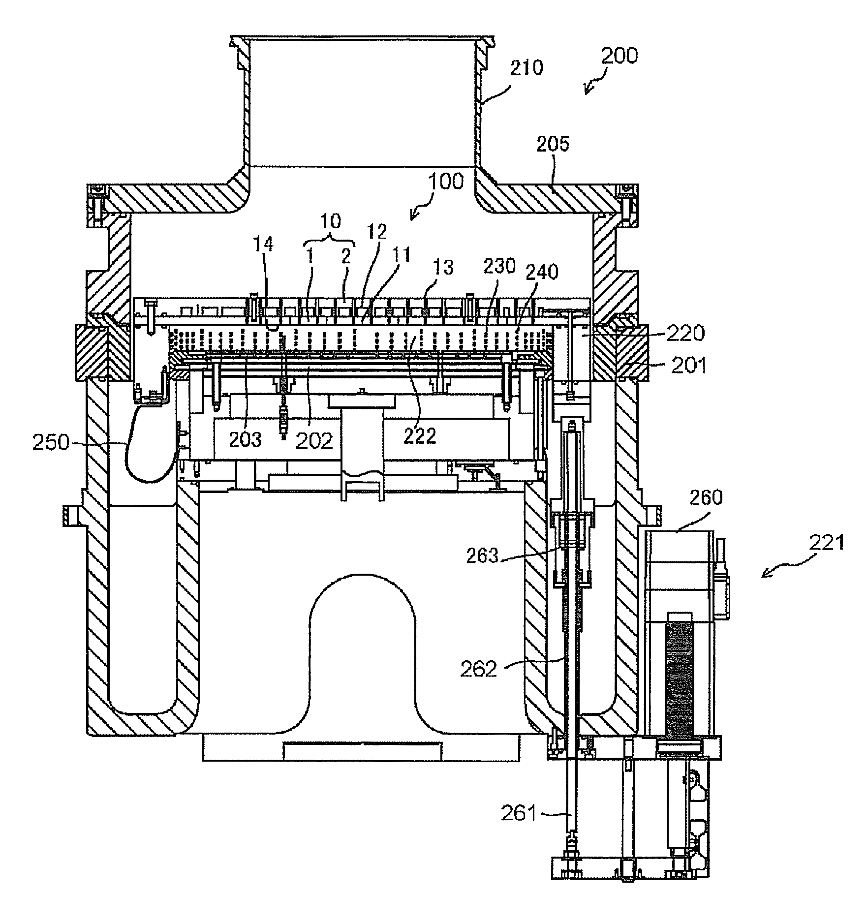
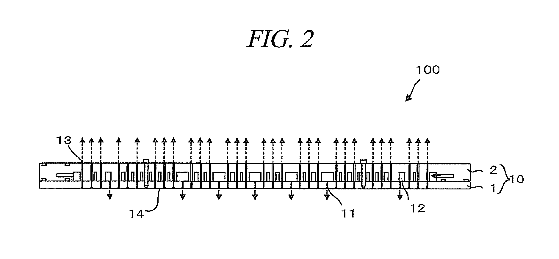
[0020]FIG. 1 is a schematic view illustrating a cross sectional configuration of a plasma etching apparatus 200 as a plasma processing apparatus in accordance with an embodiment of the present disclosure. FIG. 2 is a cross sectional view showing a schematic configuration of a shower head 100 of the plasma etching apparatus 200. The plasma etching apparatus 200 is configured as a plasma etching apparatus of a capacitively coupled parallel plate type in which upper and lower electrode plates are arranged in parallel to each other and are connected to power supplies (not shown) for plasma generation.

[0021]As illustrated in FIG. 2, the shower head 100 is made up of a layered body 10 having two sheets of plate-shaped members: a lower member 1 and an upper member 2 placed on the top of the lower member 1. By way of example, the lower member 1 and the upper membe...


PUM

PropertyMeasurementUnit
diameteraaaaaaaaaa
diameteraaaaaaaaaa
frequencyaaaaaaaaaa

Abstract

A plasma processing apparatus includes an upper electrode that is installed within a processing chamber so as to face a lower electrode, supplies a gas through a plurality of gas supply holes provided in a facing surface and is vertically movable; a cover body installed above the upper electrode so as to airtightly seal a top opening of the processing chamber; a multiple number of gas exhaust holes provided in the facing surface; a ring-shaped member that is arranged along a circumference of the upper electrode, is vertically movable along with the upper electrode, and forms, at a lowered position, a processing space surrounded by the lower electrode, the upper electrode and the ring-shaped member; a multiplicity of gas supply holes opened in an inner wall of the ring-shaped member; and a plurality of gas exhaust holes opened in an inner wall of the ring-shaped member.

Description

CROSS-REFERENCE TO RELATED APPLICATION[0001]This application claims the benefit of Japanese Patent Application No. 2009-275564 filed on Dec. 3, 2009, and U.S. Provisional Application Ser. No. 61 / 296,290 filed on Jan. 19, 2010, the entire disclosures of which are incorporated herein by reference.FIELD OF THE INVENTION[0002]The present disclosure relates to a plasma processing apparatus.BACKGROUND OF THE INVENTION[0003]In the field of manufacture of a semiconductor device or the like, a shower head for supplying a gas toward a substrate such as a semiconductor wafer in a shower pattern has been conventionally used. To be specific, in a plasma processing apparatus that performs a plasma etching process on a substrate such as a semiconductor wafer, a mounting table for mounting the substrate thereon is installed in a processing chamber, and the shower head is installed so as to face the mounting table. The shower head is provided with a multiple number of gas discharge holes on its surf...

Claims


Application Information

Patent Timeline
Patent Type & Authority Applications(United States)
IPC IPC(8): C23F1/08
CPCH01J37/32091H01J37/32568H01J37/32623C23C16/4558H01J37/3244C23C16/45563H01L21/6719
Inventor IIZUKA, HACHISHIRO
Owner TOKYO ELECTRON LTD
Why Eureka
Try Eureka