Brake actuator assembly with line replaceable motor features

a technology of electromechanical actuators and motor parts, which is applied in the direction of braking systems, aircraft braking arrangements, transportation and packaging, etc., can solve the problems of dust, debris, and/or other particulate contaminants entering the electromechanical actuator, and the electromechanical actuator is not configured

Active Publication Date: 2011-06-09
HONEYWELL INT INC
View PDF34 Cites 23 Cited by
  • Summary
  • Abstract
  • Description
  • Claims
  • Application Information

AI Technical Summary

Benefits of technology

[0009]In another embodiment, an aircraft electric brake actuator assembly includes an actuator housing, an actuator, a gear set, an electric motor, and a foreign-object-damage (FOD) shield. The actuator housing is configured to be mounted on an aircraft landing gear, and defines an actuator gearbox housing. The actuator is disposed within the actuator housing, is coupled to receive a drive torque, and is configured, upon receipt of the drive torque, to translate to a position. The gear set is disposed within the actuator gearbox housing and is coupled to the actuator. The electric motor is coupled to the actuator housing and includes an output shaft coupled to the gear set. The electric motor is configured to at least selectively supply a drive torque to the actuator via the gear set. The FOD shield is disposed between the electric motor and the actuator gearbox housing, and includes an opening through which the output shaft extends. The opening in the FOD shield is dimensioned to at least inhibit debris ingress into the gearbox housing when the electric motor is removed.
[0010]In still another embodiment, an aircraft electric brake actuator assembly includes an actuator housing, a motor housing, an actuator, a gear set, an electric motor, and a foreign-object-damage (FOD) shield. The actuator housing is configured to be mounted on an aircraft landing gear, and defines an actuator gearbox housing. The motor housing is coupled to the actuator housing and is removable therefrom. The motor housing is accessible when the actuator housing is mounted on an aircraft landing gear. The actuator is disposed within the actuator housing, is coupled to receive a drive torque, and is configured, upon receipt of the drive torque, to translate to a position. The gear set is disposed within the actuator gearbox housing and is coupled to the actuator. The electric motor is disposed within the motor housing and is coupled to the actuator housing. The electric motor includes an output shaft coupled to the gear set. The electric motor is configured to at least selectively supply a drive torque to the actuator via the gear set. The FOD shield is disposed between the electric motor and the actuator gearbox housing, and includes an opening through which the output shaft extends. The opening in the FOD shield is dimensioned to at least inhibit debris ingress into the gearbox housing when the electric motor is removed.

Problems solved by technology

However, present aircraft brake system electromechanical actuators are not configured such that the electric motor is an LRU.
In other words, present aircraft brake system electromechanical actuators are not configured to allow removal and replacement of the electric motor while the remainder of the electromechanical actuator remains installed on the aircraft.
Moreover, even if such a configuration is provided, there is a potential for dust, debris, and / or other particulate contaminants to enter the electromechanical actuator.

Method used


Image

  • Brake actuator assembly with line replaceable motor features
  • Brake actuator assembly with line replaceable motor features
  • Brake actuator assembly with line replaceable motor features

Examples


Embodiment Construction

[0020]The following detailed description is merely exemplary in nature and is not intended to limit the invention or the application and uses of the invention. Furthermore, there is no intention to be bound by any theory presented in the preceding background of the invention or the following detailed description of the invention. In this regard, before proceeding with the detailed description, it is to be appreciated that the described embodiment is not limited to use in conjunction with a specific vehicle or brake system. Thus, although the description is explicitly directed toward an embodiment that is implemented in an aircraft brake actuation system, it should be appreciated that it can be implemented in other vehicles and other brake actuation system designs, including those known now or hereafter in the art.

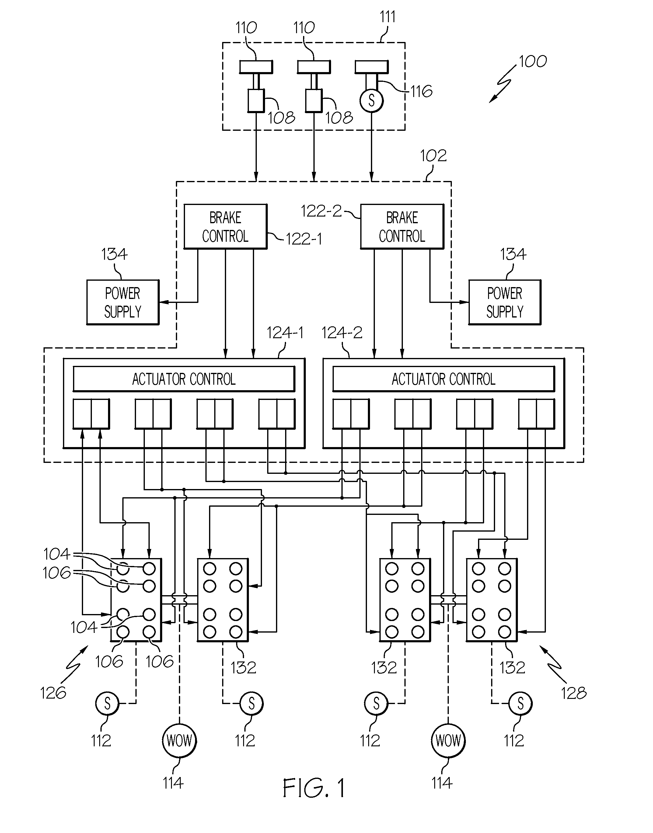
[0021]Turning now to the description, and with reference first to FIG. 1, a functional block diagram of an exemplary aircraft brake actuation system 100 is shown. In the de...


PUM


Abstract

An aircraft brake system electromechanical actuator is provided. The actuator is configured with features that allow the electric motor to be a line replaceable unit. One such feature is a foreign-object-damage shield that inhibits dust, debris, and / or other particulate contaminants from entering the electromechanical actuator during electric motor removal and replacement.

Description

CROSS-REFERENCE TO RELATED APPLICATION[0001]This application claims the benefit of U.S. Provisional Application No. 61 / 266,353, filed Dec. 3, 2009.TECHNICAL FIELD[0002]The present invention relates to aircraft brake actuation systems and, more particularly, to a brake actuation system electromechanical actuator assembly that includes features that enhance in-place motor replacement.BACKGROUND[0003]When a jet-powered aircraft lands, the aircraft brakes, various aerodynamic drag sources (e.g., flaps, spoilers, etc.), and, in many instances, aircraft thrust reversers, are used to slow the aircraft down in the desired amount of runway distance. Once the aircraft is sufficiently slowed, and is taxiing from the runway toward its ground destination, the aircraft brakes are used to slow the aircraft, and bring it to a stop at its final ground destination.[0004]Presently, many aircraft brake systems include a plurality of hydraulic, pneumatic, or electromechanical actuators, and a plurality ...

Claims


Application Information

Patent Timeline
Patent Type & Authority Applications(United States)
IPC IPC(8): F16D65/18B64C25/44
CPCF16D2121/24F16D65/0043B60T13/741B60T7/042F16D2127/06F16D65/18F16D65/28B60T7/085F16D2125/40F16D2125/48
Inventor HANLON, CASEYGECK, KELLANQUITMEYER, JAMES NEILBLUNT, ALLAN
Owner HONEYWELL INT INC
Why Eureka
Try Eureka