Image processing apparatus and image processing method

Inactive Publication Date: 2011-06-09
CANON KK
View PDF6 Cites 21 Cited by
  • Summary
  • Abstract
  • Description
  • Claims
  • Application Information

AI Technical Summary

Benefits of technology

[0020]The present invention can generate a high-resolution, low-noise tomogram while mi

Problems solved by technology

However, the resolution of each tomogram remains the same, and hence it is difficult to generate a high-resolution tomogram by combining the tomograms.
The tomograms to be captured become susceptible to the influences of movements or flicks of the eyeballs by the patient during scanning, the movement of the head,

Method used


Image

  • Image processing apparatus and image processing method
  • Image processing apparatus and image processing method
  • Image processing apparatus and image processing method

Examples


Example

First Embodiment

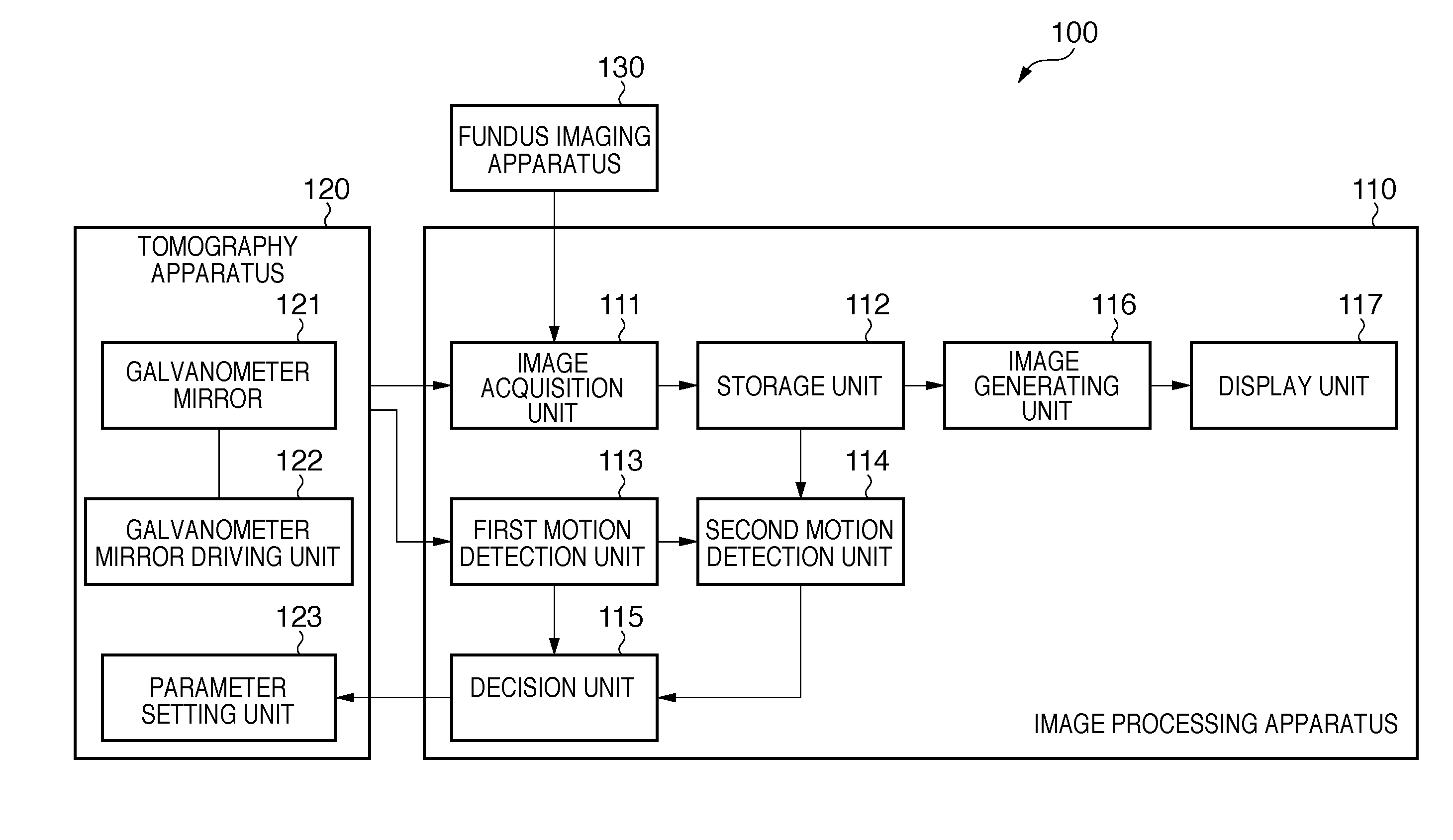
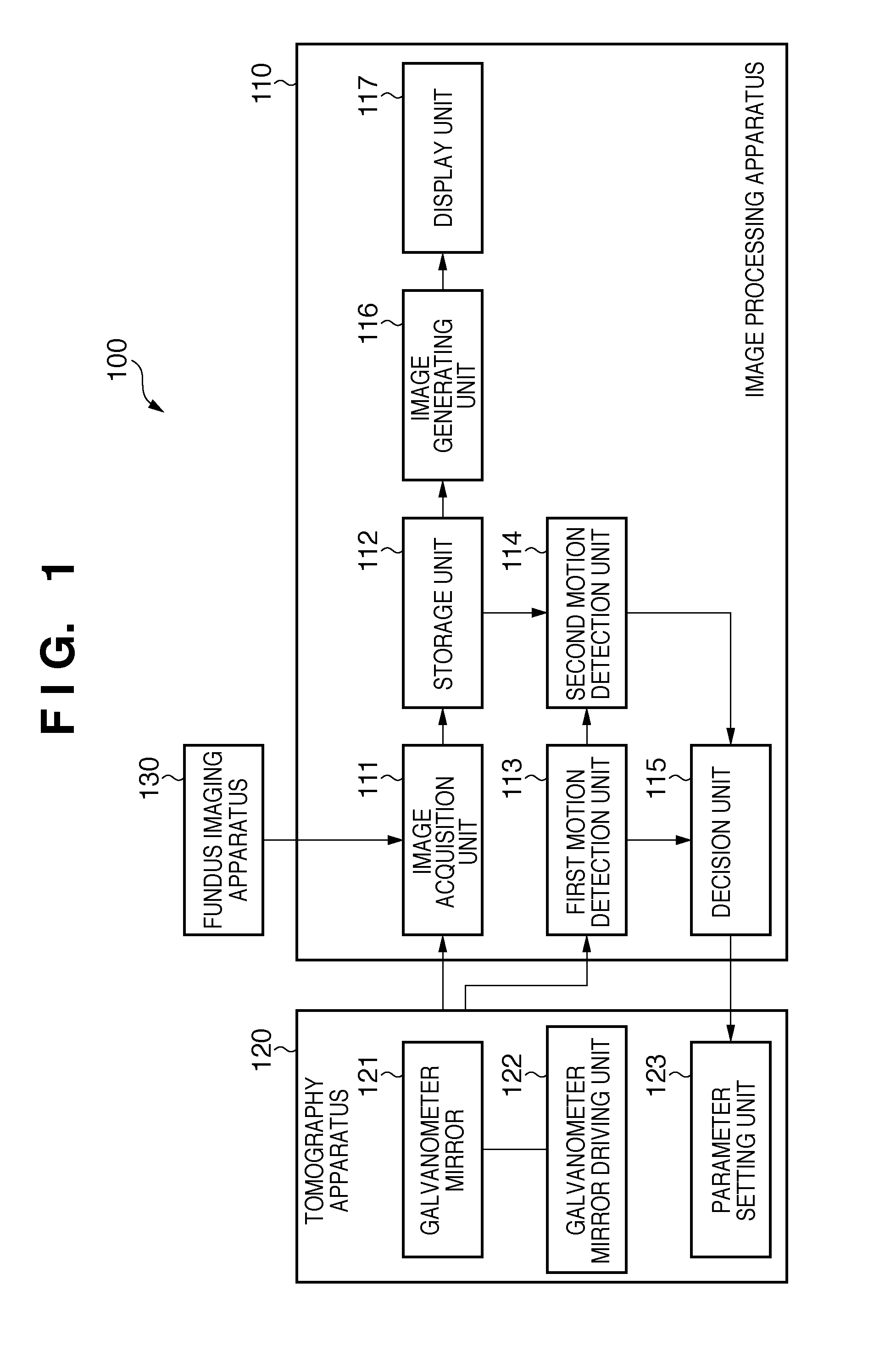
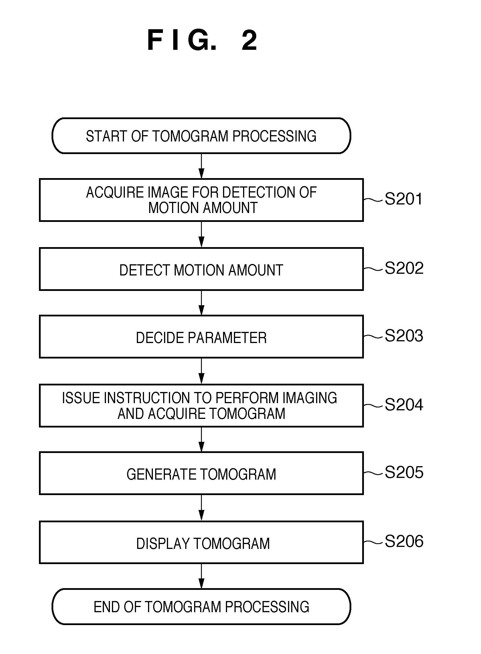
[0034]The first embodiment of the present invention will be described below with reference to the accompanying drawings. A characteristic feature of an image processing apparatus according to this embodiment is that it detects the motion amount of an eye to be examined (per unit time) when performing imaging by the oversampling method or the averaging method and performs imaging based on imaging conditions corresponding to the detected motion amount.

[0035]This embodiment is configured to perform imaging using the oversampling method or the averaging method under imaging conditions corresponding to the motion amounts of the eyes of each individual, and hence can generate a low-noise, high-resolution tomogram while minimizing the influences of movement of the individual's eyeballs, the head or the like.

[0036]An image processing system including an image processing apparatus according to this embodiment will be described in detail below.

[0037]

[0038]FIG. 1 is a block dia...

Example

Second Embodiment

[0090]The first embodiment described above is configured to perform imaging for the detection of motion amounts to set imaging conditions and capture a tomogram again. However, the present invention is not limited to this. For example, when performing imaging under predetermined imaging conditions and processing an acquired tomogram, the present invention may be configured to perform processing corresponding to the motion amounts of the eye. This embodiment will be described in detail below.

[0091]

[0092]FIG. 6 is a block diagram showing the arrangement of an image processing system 600 including an image processing apparatus 610 according to this embodiment. As shown in FIG. 6, the image processing system 100 described in the first embodiment differs in functional arrangement from the image processing apparatus 610. The differences between the functional arrangements will be mainly described below.

[0093]As shown in FIG. 6, the image processing apparatus 610 includes ...

Example

Third Embodiment

[0111]The first embodiment described above is configured to decide parameters based on the tomogram and fundus image acquired by imaging for the detection of the motion amounts of the eye and process the tomogram acquired by imaging using the decided parameters. However, the present invention is not limited to this. For example, the present invention may be configured to detect motion amounts even while performing imaging using decided parameters, decide parameters again upon detecting a motion amount equal to or more than a predetermined threshold, and automatically redo imaging.

[0112]This makes it possible to keep generating tomograms with high image quality even if a large change, for example, blinking or microsaccades, occurs during imaging, because parameters are set again based on the motion amounts detected during imaging.

[0113]This embodiment will be described in detail below with reference to FIG. 8. Note that the functional arrangement of an image processin...


PUM


Abstract

This invention can generate a high-resolution, low-noise tomogram while minimizing the influences of the flicks of the eyeballs, the movement of the head, and the like. The invention is an image processing apparatus which processes a tomogram of an eye to be examined and includes detection units to detect the motion amount of the eye by using a signal obtained by capturing the tomogram, and a decision unit to decide the number of scanning lines for capturing of the tomogram based on the motion amount detected by the detection units.

Description

BACKGROUND OF THE INVENTION[0001]1. Field of the Invention[0002]The present invention relates to an image processing apparatus and image processing method which process the tomograms captured by the tomography apparatus.[0003]2. Description of the Related Art[0004]An ophthalmic tomography apparatus such as an optical coherence tomography (OCT) apparatus is configured to generate an image (or tomogram) of a retina from a signal produced through the interference between near-infrared light reflected from the retina and reference light. In general, the image quality of a tomogram generated based on interference light in this manner depends on the intensity of near-infrared light striking the retina. In order to improve the image quality of a tomogram, it is necessary to increase the intensity of near-infrared light applied to the retina. The intensity of near-infrared light which can be applied to the retina has a certain limit from the viewpoint of safety.[0005]It is therefore require...

Claims


Application Information

Patent Timeline
IPC IPC(8): A61B3/14
CPCG06T7/0012G06T2207/30041G06T2207/10101
Inventor IWASE, YOSHIHIKOKATAYAMA, AKIHIRO
Owner CANON KK
Why Eureka
Try Eureka