High power device module

a high-power device and module technology, applied in the direction of electrical equipment, electrical equipment construction details, conversion construction details, etc., can solve the problems of unsatisfactory function design of high-power device modules, and achieve the effects of high power application, high tensile strength, and high power device modules

a high-power device and module technology, applied in the direction of electrical equipment, electrical equipment construction details, conversion construction details, etc., can solve the problems of unsatisfactory function design of high-power device modules, and achieve the effects of high power application, high tensile strength, and high power device modules

US20110134619A1Inactive Publication Date: 2011-06-09LIN CHIN FENG

Image

  • High power device module
  • High power device module
  • High power device module

Examples


Embodiment Construction

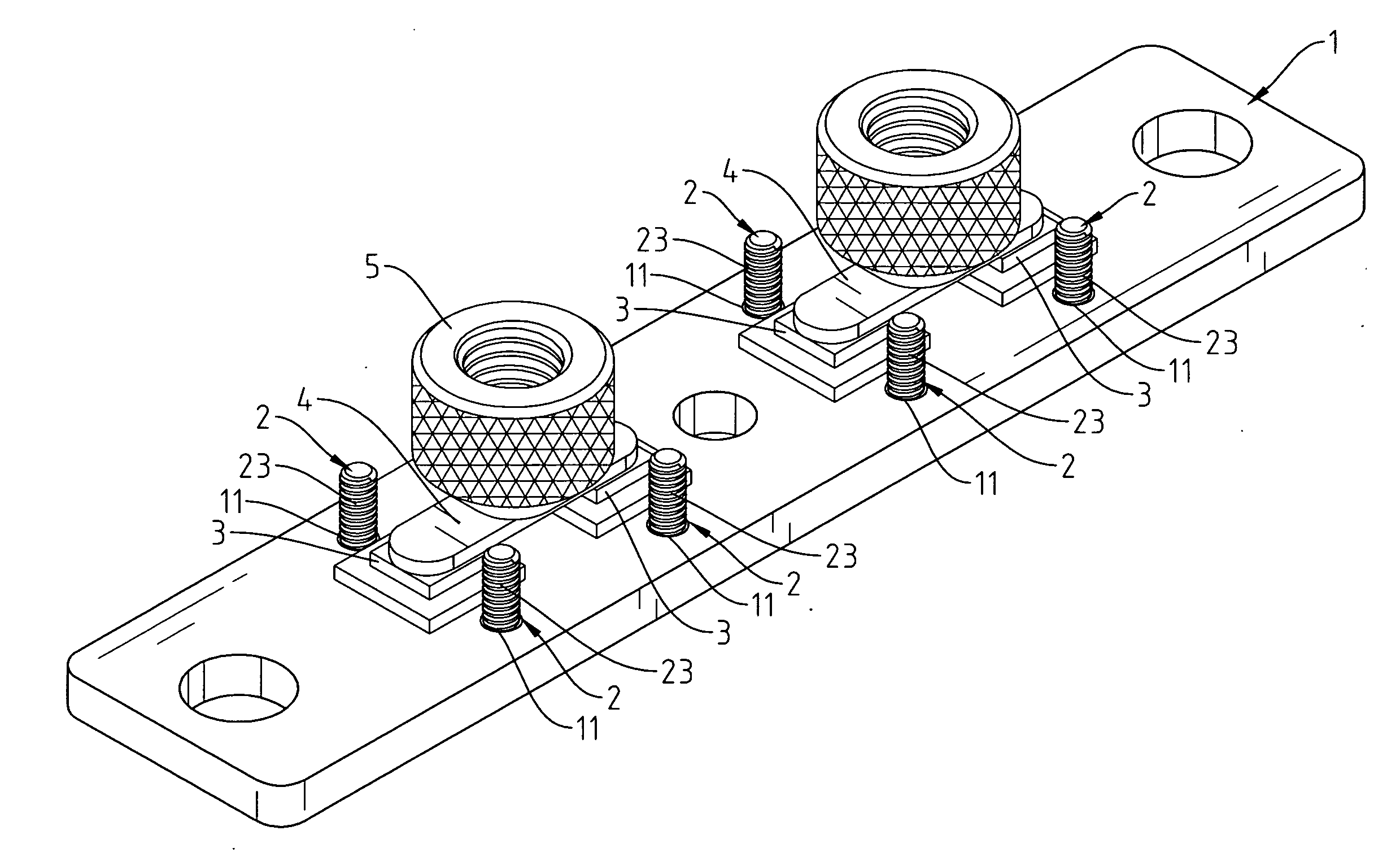
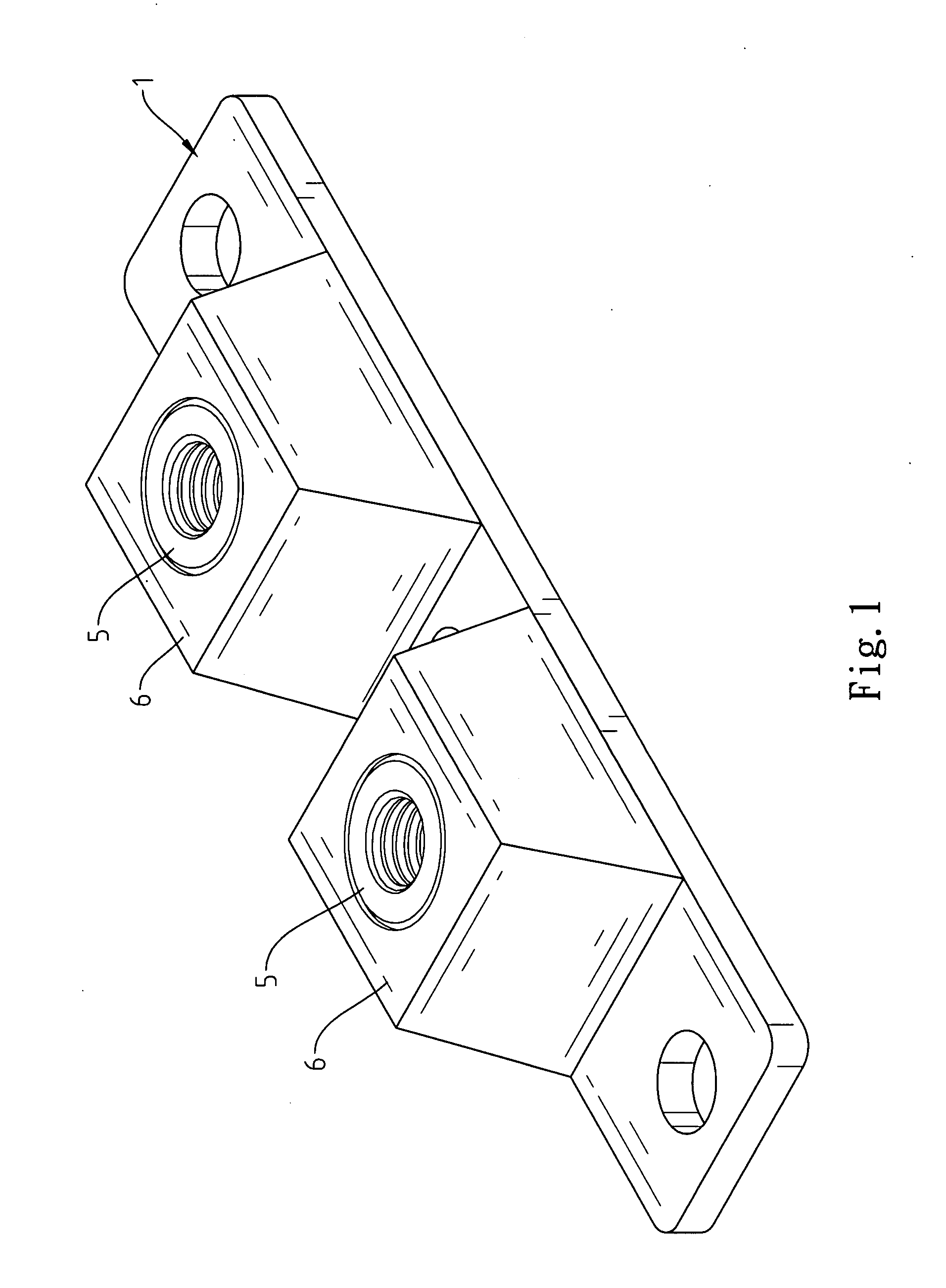
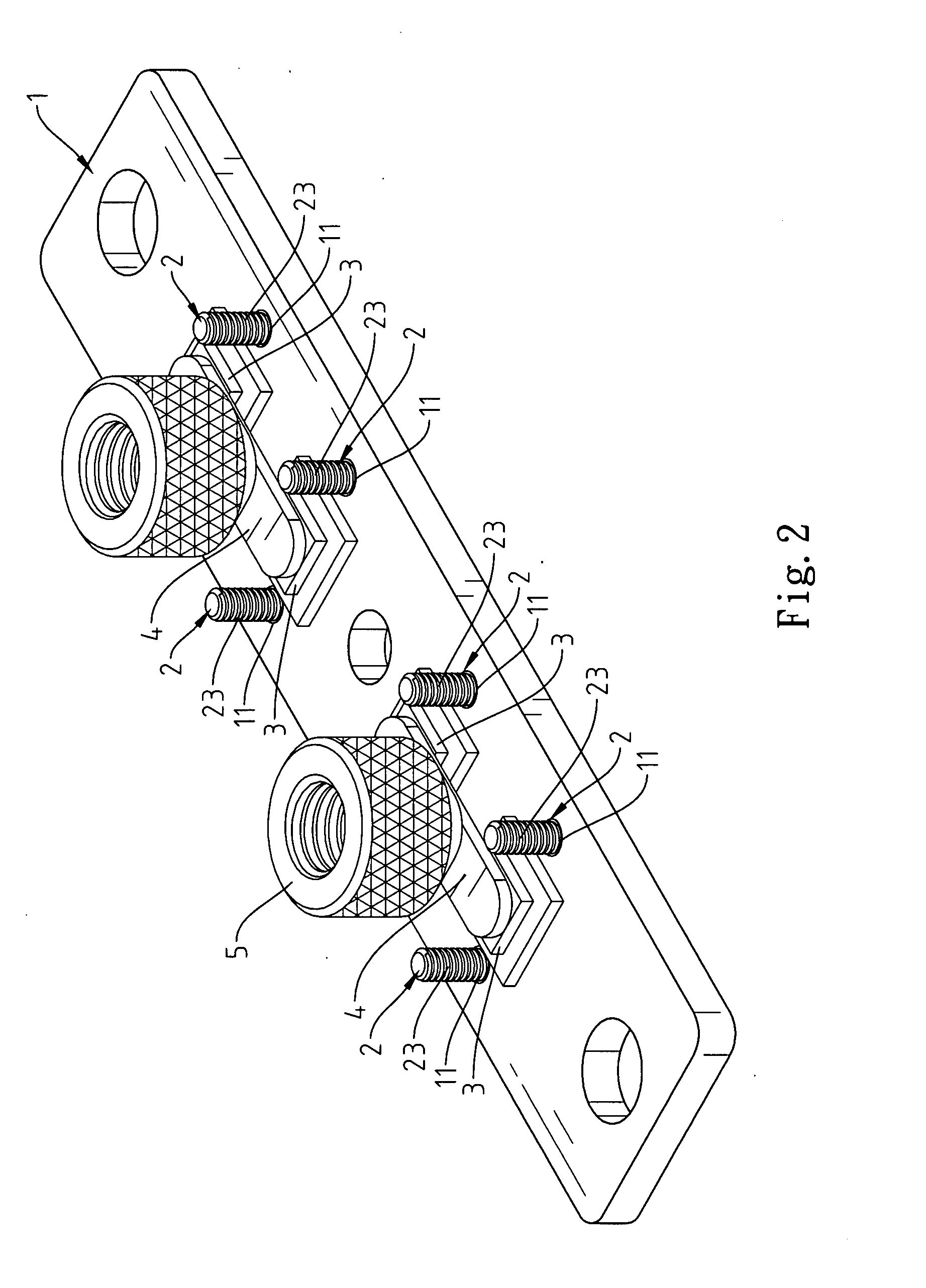
[0013]Referring to FIGS. 1-3, a high power device module in accordance with the present invention is shown comprising a substrate 1, and a plurality of fastening members 2 installed in the substrate 1. The substrate 1 has a plurality of through holes 11 cut through its top and bottom sides. The through holes 11 are stepped through holes, each having an expanded bottom end 111. The fastening members 2 are respectively mounted in the through holes 11 of the substrate 1, each comprising a head 21, a shank 23, and a shoulder 22 connected between the shank 23 and the head 21.

[0014]Referring to FIGS. 4 and 5 and FIG. 3 again, the fastening members 2 are respectively inserted into the through holes 11 from the bottom side of the substrate 1 to have the respectively shoulders 22 respectively fitted into the through holes 11 and the respective heads 21 respectively fitted into the expanded bottom ends 111 of the through holes 11 and the respective shanks 23 protruding over the top side of th...


PUM


Abstract

A high power device module includes a substrate carrying multiple chips on the top side and having stepped through holes around the chips, copper plates and connectors connected to the chips, fastening members each having a shoulder respectively fitted into the through holes of the substrate, a head connected to one end of the shoulder fitted into the expanded bottom end of the associating stepped through hole, and a shank connected to the other end of the shoulder and protruding over the top side of the substrate, and packaging members directly molded from resin on the shanks of the fastening members and the chips and the copper plates and the connectors to seal the component parts to the substrate.

Description

BACKGROUND OF THE INVENTION[0001]1. Field of the Invention[0002]The present invention relates to a high power device module for high power application and more particularly, to such a high power device module, which is strong enough to bear a high gravity weight.[0003]2. Description of the Related Art[0004]Following the development and integration of technology, power electronic devices and control techniques are well developed. In addition to the application for electric energy conversion and energy saving, power electronic technology has also been intensively used in many other different fields to improve our living quality. Facing global free dissemination of electrical industry, utilization of recycling energy and development of new energy, advanced countries are trying hard in integration of power supply, electronics, and electromechanics.[0005]FIG. 6 illustrates the internal structure of a conventional high power device module. According to this design, screws 20 are mounted i...

Claims


Application Information

Patent Timeline
09 Jun 2011
Publication
US20110134619A1
IPC
H05K7/00
CPC
H02M7/003
Inventors
LIN, CHIN-FENG