Dual electrolyte membraneless microchannel fuel cells

a fuel cell and membraneless technology, applied in the field of microfluidic flow cells, can solve the problems of increasing the complexity of the network structure, increasing the cost, and reducing the thickness, and achieve the effect of high power devices and high power systems

Inactive Publication Date: 2006-10-12
CORNELL RES FOUNDATION INC
View PDF11 Cites 49 Cited by
  • Summary
  • Abstract
  • Description
  • Claims
  • Application Information

AI Technical Summary

Benefits of technology

[0016] The planar membraneless microfluidic fuel cell designs provided herein have several advantages over previous designs. In particular, the fuel designs herein take advantage of the laminar flow conditions that exist between two large parallel plates with a microscopic separation between them. As described hereinbelow in greater detail (see FIG. 1), a preferable embodiment of the present invention uses a structure referred to as a “flow control structure,” and is designed to establish a condition of laminar flow of two solution streams flowing on either side of the flow control structure prior to the two streams coming into contact. The flow control structure may also be referred to as a “tapered cantilever” (see U.S. provisional patent application Ser. No. 60 / 579,075, which is incorporate by reference herein). In some preferable embodiments, the cantilever includes a taper at its thin edge that is tapered down to as thin a structure as can be obtained by a chemical etching process, such as a few atomic diameters or virtually zero thickness, but just thick enough to maintain structural integrity. In other alternate embodiments, the taper at its thin edge is as thick as 50 microns. In some embodiments, the flow control structure is tapered on only one side, or is tapered on both sides. In some embodiments, in which tapers are present on both sides, it is contemplated that the taper angles may or may not be equal or symmetric when measured with respect to a boundary layer between the two fluids. In some embodiments, there is no taper on the flow control structure. The advantages that accrue when adopting the planar microfluidic configuration over other (e.g. microchannel) configurations include:
[0017] a deposition of electrode materials becomes a manageable process based on sputtering and / or evaporation techniques,
[0018] the large solution / electrode interfacial area available in this design can lead to higher power devices,
[0019] the stacking of devices can lead to potentially high power systems taking up small volumes, and

Problems solved by technology

One of the most challenging aspects of the miniaturization of fuel cells is attributed to the reliance on the PEM component, which itself suffers from numerous problems including: drying out of the membrane (especially at high operating temperatures), fuel crossover into the oxidizer, in addition to the high expense typically associated with membrane development.
All of these problems are further compounded by the need to decrease the thickness (further increasing the complication of the network structure) of the PEM when designing a micro-fuel cell.
While these enzymatic redox systems can provide the desired selectivity, they typically generate very low power and suffer from all of the problems attendant to the use of enzymes, with long-term stability being especially problematic.
The PEM also takes up much of the space in the non-enzymatic micro-fuel cells being developed, thus limiting the size of the final device.
Despite significant advances in PEM fuel cells that have been achieved in the last decade, there are still a number of unresolved issues that have limited their use.
The PEM remains a relatively expensive and often unreliable component of PEM fuel cells.
Thus, one of the more serious complicating factors (among numerous others) in the miniaturization of fuel cells has been the instability of the PEM and the membrane electrode assembly under operating conditions.
Due to the approach used, the only way to increase the interface area would be to increase channel depth (which may be difficult or costly to achieve using certain manufacturing techniques such as photolithography, which also has difficulty producing large vertical walls) and / or to increase channel length (the maximum useful length may be limited however by the dynamics of parallel and laminar flow).
Either attempt to increase the interface area would present other considerations and additional problems that would need to be addressed.
Since the amount of a substance that can be caused to react is proportional to the area, of the interface between the two laminar flows, one problem that needs to be solved is how to arrange for larger areas of the interface between such laminar flows and also to increase the interface area without also increasing the volume of fluid.
Nevertheless it has been observed that the resulting thermodynamic potentials from these single electrolyte systems remain relatively modest.

Method used


Image

  • Dual electrolyte membraneless microchannel fuel cells
  • Dual electrolyte membraneless microchannel fuel cells
  • Dual electrolyte membraneless microchannel fuel cells

Examples


example

Fuel Cell Assembly

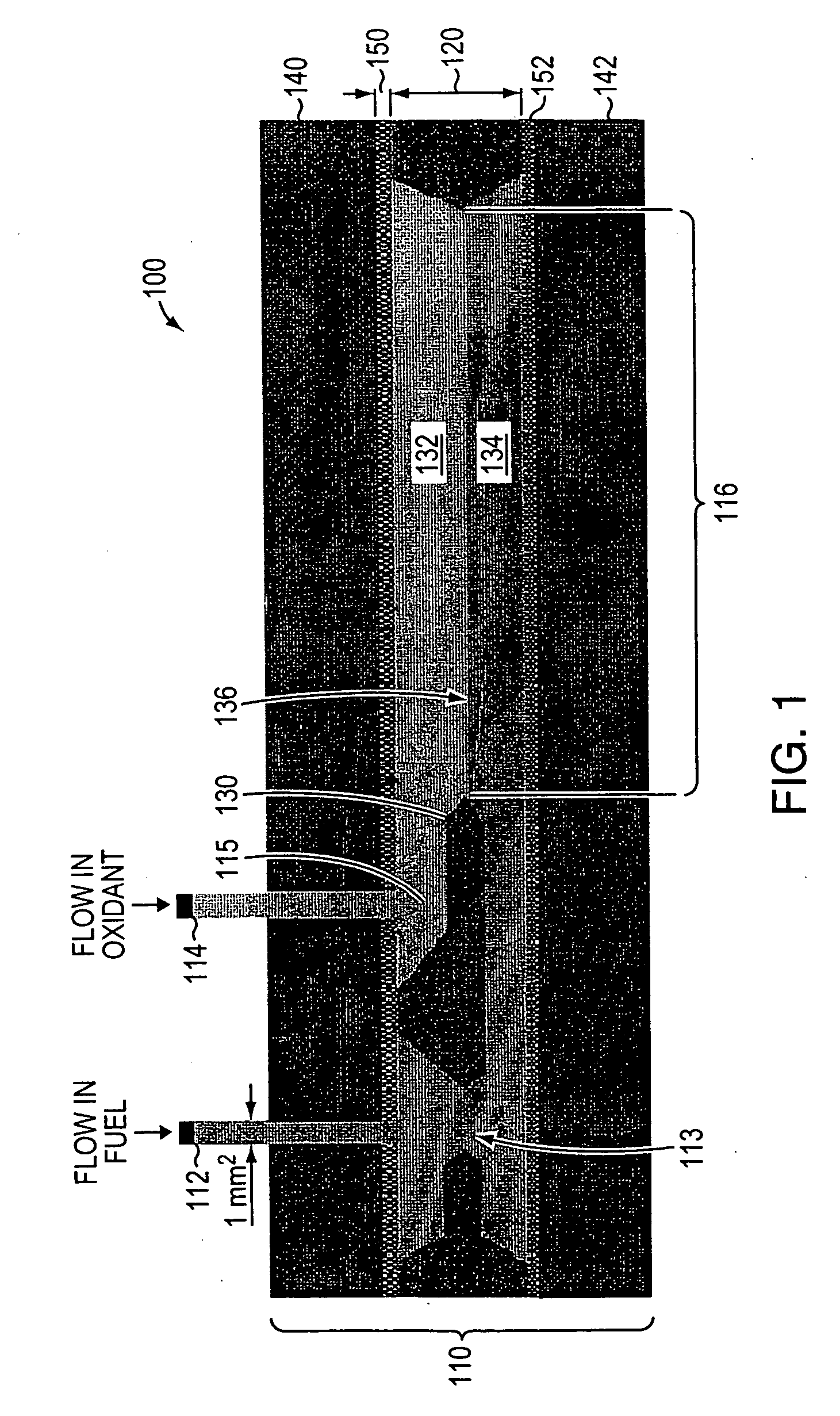
[0098] After establishing that the proposed planar design generates laminar flow inside the microchannels, fabricated microchannels and electrodes were integrated into a fuel cell embodiment that illustrates various principles of the invention, including affording deliberate control over system parameters. The silicon microchannels were aligned in a Plexiglas cell with Kapton®-based platinum electrodes placed on the top and bottom of the microchannel, and were clamped together using bolts, as shown in FIGS. 5-6.

[0099]FIG. 6 is a picture that shows an example of a silicon microchannel flow cell configured as a micro-fuel cell 600. In this fuel cell 600, a silicon microchannel 505 is provided. Two input tubes 510, 515 provide fluids that enter the silicon microchannel 505 from the same face, namely the top surface in the embodiment shown in FIG. 6. In the embodiment of FIG. 6, the two input tubes 510, 515 were attached to the flow cell shown with epoxy. However, an...


PUM

PropertyMeasurementUnit
weightaaaaaaaaaa
thicknessaaaaaaaaaa
thicknessaaaaaaaaaa

Abstract

A microfluidic membraneless flow cell formed with multiple acidic/alkaline electrolyte solutions. The flow cell can be adapted to provide a dual electrolyte H2/O2 fuel cell that generates thermodynamic potentials of up to 1.943 V or possibly greater. The selected fuel can be hydrogen dissolved in 0.1 M KOH, and the selected oxidant can be oxygen dissolved in 0.1 M H2SO4. Individual fuel cells can be combined to form fuel cell stacks to generate increased power output. Furthermore, microchannels of varying dimensions may be selected, including thickness variations, and different flow rates of acid/base electrolyte solutions can be applied to satisfy predetermined power generation needs. Some (micro-) fuel cell embodiments can be formed with silicon microchannels of fixed length and variable width and height, and can be used with hydrogen or formic acid as a fuel and oxygen as an oxidant, each dissolved in different acid/base electrolyte solutions. Micro-fuel cells are also provided which can be designed to generate different power levels for various applications including portable electronic devices such as wireless communication handsets and cellular telephones.

Description

CROSS-REFERENCE TO RELATED APPLICATIONS [0001] This application is a continuation-in-part application of U.S. patent application Ser. No. 11 / 150,622 filed on Jun. 10, 2005, which claims the benefit of priority to U.S. provisional patent application Ser. No. 60 / 579,075 filed on Jun. 10, 2004, and to U.S. provisional patent application Ser. No. 60 / 629,440 filed on Nov. 19, 2004, which are each incorporated herein by reference in their entirety.STATEMENT REGARDING FEDERALLY FUNDED RESEARCH OR DEVELOPMENT [0002] The invention described herein was made in the performance of work under Army Research Office contract DAAD19-03-C-0100, under NSF contract ACT-0346377, and under NSF Grant ECS-0335765, and is subject to the provisions of Public Law 96-517 (35 U.S.C. §202) in which the Contractor has elected to retain title.FIELD OF THE INVENTION [0003] The invention relates to microfluidic flow cells in general, and more particularly, to electrolyte mixtures that may contain separate alkaline a...

Claims


Application Information

Patent Timeline
Patent Type & Authority Applications(United States)
IPC IPC(8): H01M6/24H01M8/08
CPCH01M8/006H01M8/026Y02E60/50H01M8/04082H01M8/0289
Inventor COHEN, JAMIE L.VOLPE, DAVID J.ABRUNA, HECTOR D.
Owner CORNELL RES FOUNDATION INC
Why Eureka
Try Eureka