Connector and operating method thereof

a technology of connecting base and shielding twisted pair, which is applied in the direction of coupling device connection, coupling device two-part connection, coupling/disengagement of coupling parts, etc., can solve the problems of high cost, time and labor cost, and better shielding of twisted pair cables, so as to improve the engagement of the wire-carrying cover and the connecting base.

Active Publication Date: 2011-06-09
EMCOM TECH
View PDF5 Cites 6 Cited by
  • Summary
  • Abstract
  • Description
  • Claims
  • Application Information

AI Technical Summary

Benefits of technology

[0015]In addition, in step 1, the step of pressing the signal transmitting unit further includes assembling a connecting base with the assembly hole of the connector body, and electrically coupling a wire-carrying cover with the connecting base. In step 4, the method further includes pressing the top end of the wire-carrying cover by a pressing board extending from the pressing portion to enhance the engagement of the wire-carrying cover and the connecting base. In a preferred embodiment, the method further includes adjusting a distance between the fastening plate and the second pivot and a distance between the third pivot of the extension plate and the pressing portion to change an angle of the initial engaging position and a pressing force. The angle that the fastening plate moves from the initial engaging position to the engaging position is between 0 degree and 155 degrees.

Problems solved by technology

There are generally two types of twisted-pair cables including shielded twisted-pair (STP) cables and unshielded twisted-pair (UTP) cables, wherein the shielded twisted-pair cable is better in shielding electromagnetic radiations but much more expensive.
However, for constructing an enterprise LAN, a plenty of time and labor cost are necessary when employing the clip 40 to assemble the wire-carrying cover 10 with the body 30.

Method used


Image

  • Connector and operating method thereof
  • Connector and operating method thereof
  • Connector and operating method thereof

Examples


Embodiment Construction

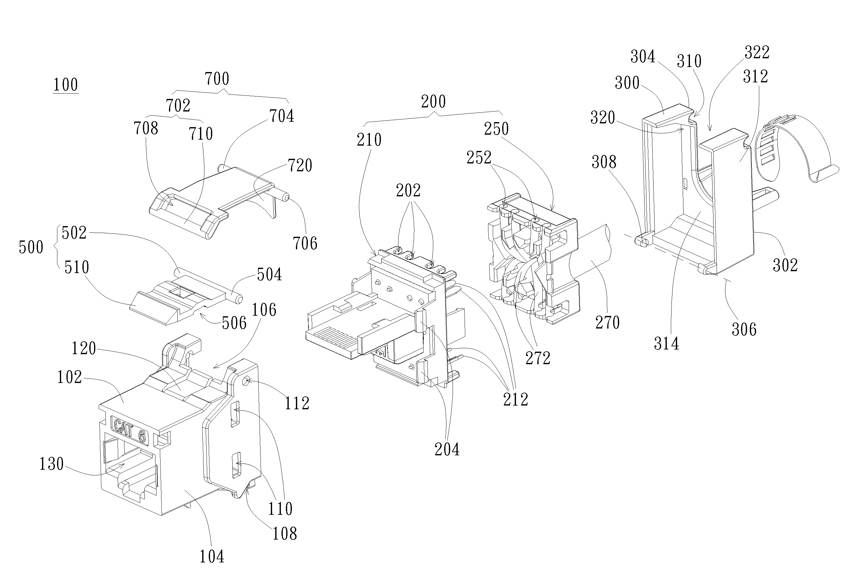
[0029]The present invention provides a connector which can save assembling time and labor cost and an operating method thereof. In a preferred embodiment, the connector is a network connector such as RJ45, and can be optionally formed as a metal shielding connector which can prevent electromagnetic interference (EMI). However, in other embodiments, the connector can be applied to universal serial bus (USB) connector or other types of connectors. The connector can be made of plastics or other materials such as electrically conductive or magnetically conductive materials. The detailed structure and operation steps will be described below with reference to figures.

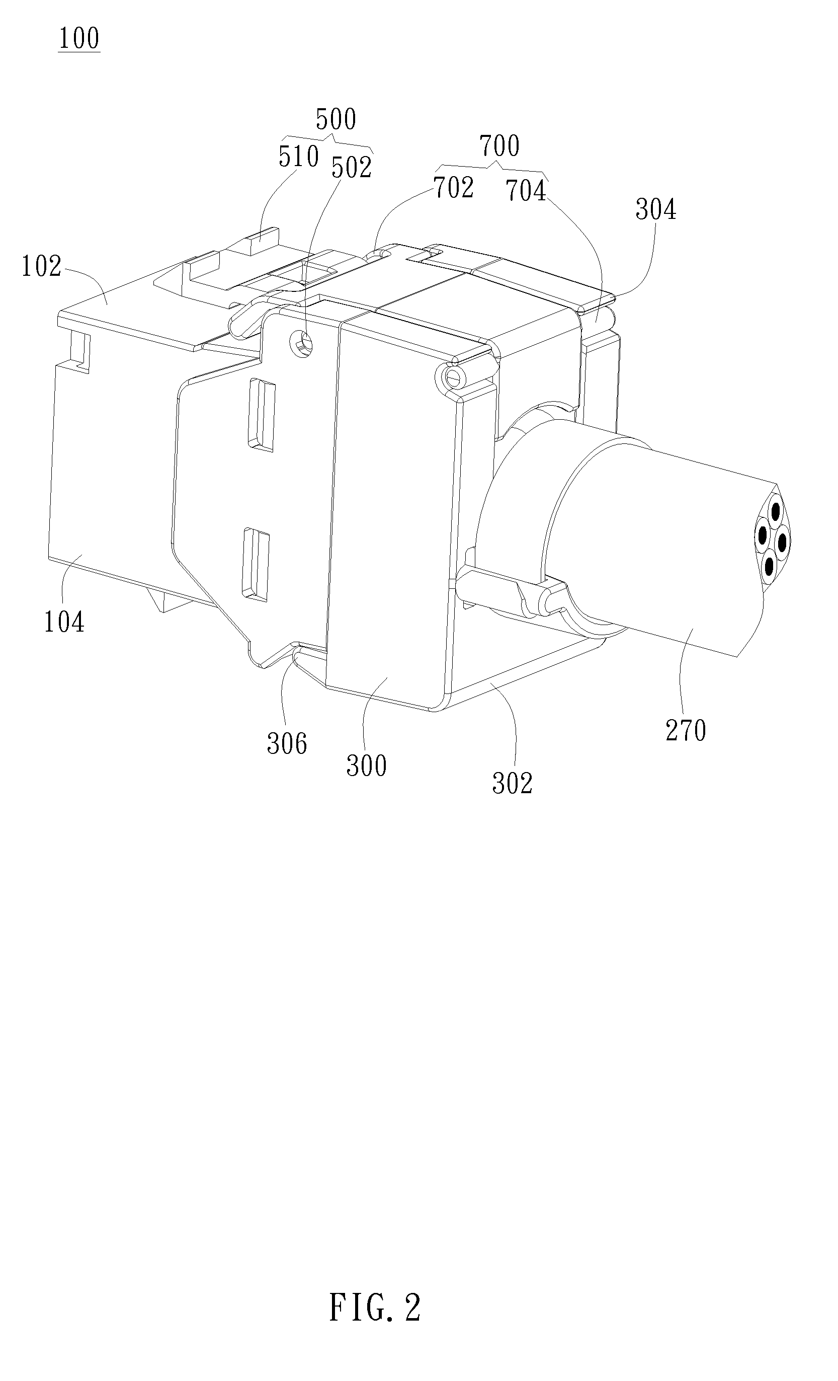
[0030]As shown in FIG. 2 and FIG. 3, the present invention provides a connector 100 including a connector body 102, a signal transmitting unit 200, a cover 300, a fastening plate 500, and an extension plate 700. The connector body 102 has several side walls 104 to enclose an assembly hole 106 on one side. Opposite to the asse...


PUM


Abstract

A connector is provided. The connector includes a connector body, a signal transmitting unit, a cover, a fastening plate, and an extension plate. The connector body has side walls to enclose an assembly hole. The signal transmitting unit is disposed in the assembly hole. The cover has a first end, a second end, and a first pivot and is disposed outside the assembly hole. The first end and the first pivot are disposed on two ends of a side case of the cover. The second end is opposite to the first end while the first pivot is axially connected to one side of the assembly hole. The fastening plate has a second pivot opposite and parallel to the first pivot. The second pivot axially connected to the side wall around the assembly hole. One end of the extension plate has a third pivot parallel to the first pivot and is rotatably connected to the fastening plate. The other end of the extension plate has a pressing portion to press the second end of the cover from outside to make the cover rotates toward the connector body and press the signal transmitting unit.

Description

CROSS REFERENCE TO RELATED APPLICATIONS[0001]This application claims priority based on a Taiwanese Patent Application No. 098141615, filed on Dec. 4, 2009, the disclosure of which is incorporated herein by reference in its entirety.BACKGROUND OF THE INVENTION[0002]1. Field of the Invention[0003]The present invention relates to a connector; particularly, the present invention relates to a connector capable of fastening the wire-carrying cover without using an auxiliary tool.[0004]2. Description of the Related Art[0005]Generally speaking, twisted-pair (TP) cables are the most prevalent network cable used in a local area network (LAN). The twisted-pair cable is composed of four pairs of different color wires (totally eight wires). Twisted-pair cables have the advantages of low cost, high connection reliability, easy maintenance, and high speed, such as 1000 Mbps or more. Twisted-pair cables can be applicable not only for data transmission but also for signal transmission such as voice ...

Claims


Application Information

Patent Timeline
Patent Type & Authority Applications(United States)
IPC IPC(8): H01R13/62
CPCH01R13/506H01R24/64H01R13/5829
Inventor WANG, CHU-LI
Owner EMCOM TECH
Why Eureka
Try Eureka