Rotary, Internal Combustion Engine

Active Publication Date: 2011-06-16
GOTEK ENERGY
View PDF53 Cites 21 Cited by
  • Summary
  • Abstract
  • Description
  • Claims
  • Application Information

AI Technical Summary

Benefits of technology

[0032]When the detailed description discusses a reference numeral in one or more drawing figures, the element and reference numeral being discussed

Problems solved by technology

Consequently, internal combustion engines can travel long distance while carrying all their fuel.
Gasoline piston engines are among the least efficient internal combustion engine, only about 25%-30% effici

Method used


Image

  • Rotary, Internal Combustion Engine
  • Rotary, Internal Combustion Engine
  • Rotary, Internal Combustion Engine

Examples


Embodiment Construction

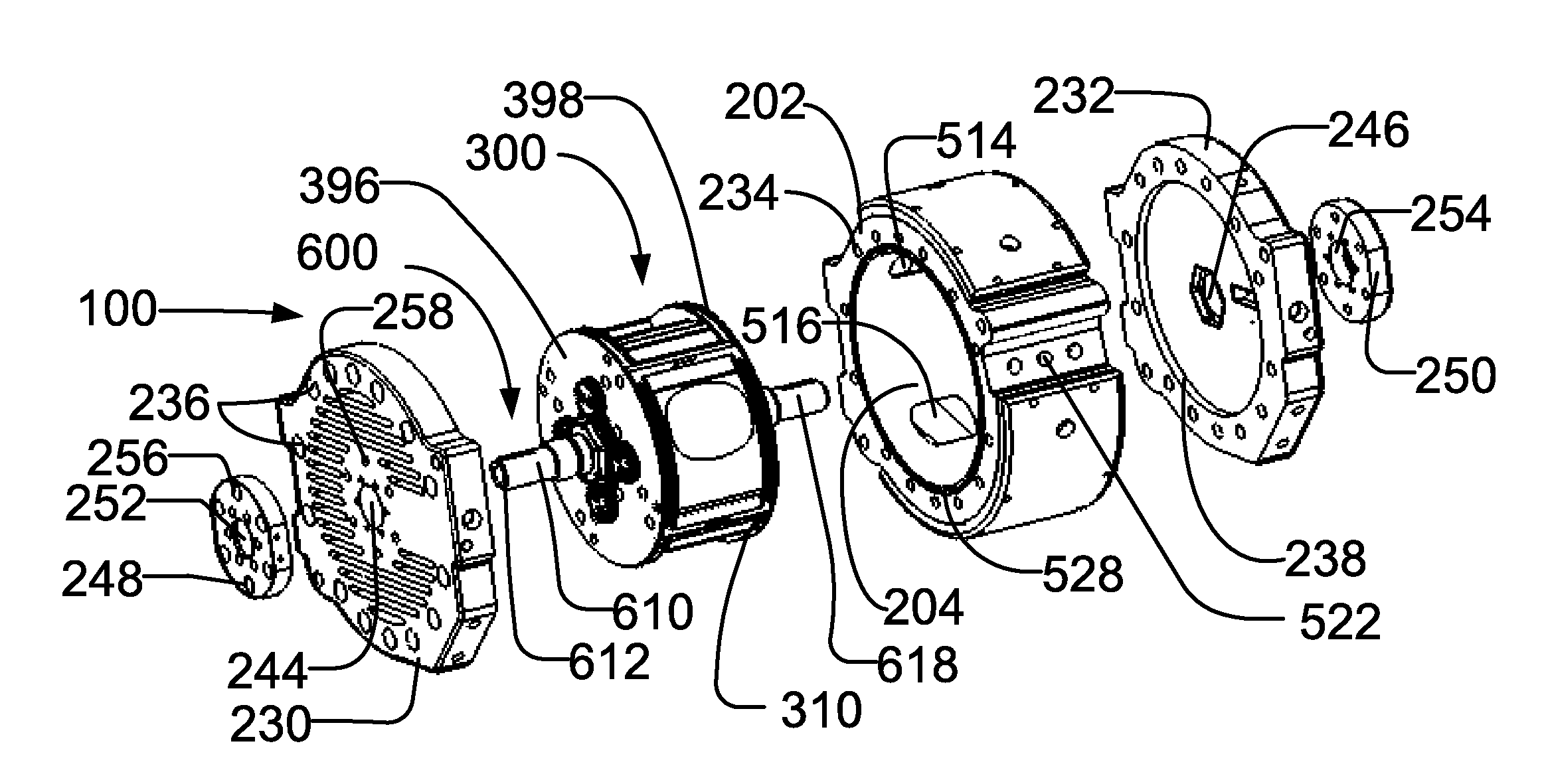
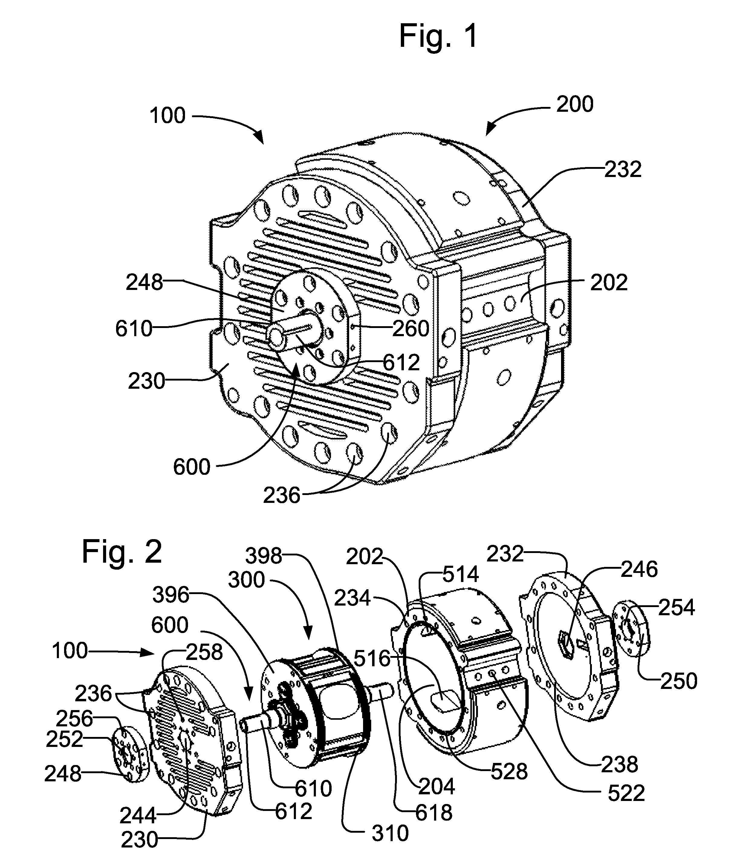
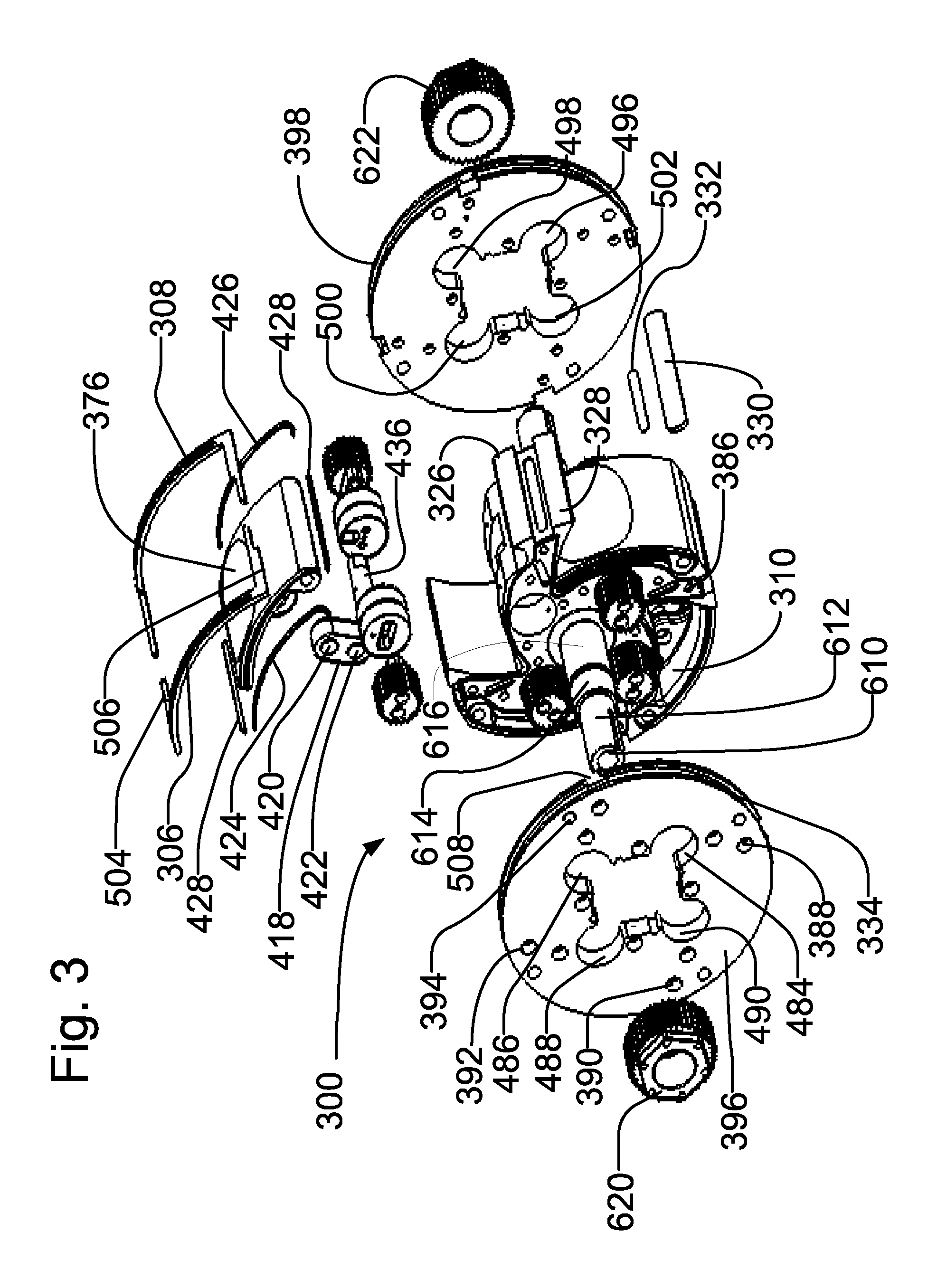
[0035]Rotary engine 100 (FIGS. 1 and 2) has the following principal components: (1) housing 200 for housing other components and for mounting in a vehicle or other device; (2) power module 300 and output 600. See FIG. 2.

[0036]Housing 200 (FIGS. 1, 4, 9 and 10) may include a generally cylindrical housing body 202 of 8620, 8514 or other steel alloy. Aluminum or other suitable materials also could be used. The housing has a cylindrical inner wall 204. The inner wall also could be a steel insert inside an aluminum outer housing body.

[0037]The housing may be air- or water-cooled. If water-cooled, the housing body may have top and bottom water troughs 210 and 220 (FIGS. 9 and 10). Top water jacket 212, which covers the top water trough, has inlet 214 and outlet 216 (FIG. 10). Likewise, bottom water jacket 222, which covers the bottom water trough, has inlet 224 and outlet 226. The inlets may receive coolant from a radiator or other heat exchanger, and the outlets return the coolant to the...


PUM


Abstract

A rotary engine has a rotor that has rockers pivoting in chambers. As each rocker pivots, it rotates an outer crankshaft. Each outer crankshaft has a spur gear that engages a stationary ring gear. Spur gear rotation causes the gears and the outer crankshafts to revolve around the ring gear. This cause the rotor to rotate. As the rotor rotates, successive chambers are positioned at the intake, compression, ignition, and exhaust positions. Igniting the fuel in the ignition position pushes the rocker inward to rotate the outer crankshaft associated with that rocker to cause the rotor to rotate.

Description

NOTICE OF COPYRIGHTS AND TRADE DRESS[0001]A portion of the disclosure of this patent document contains material that is subject to copyright protection. This patent document may show or describe matter that is or may become trade dress of the owner. The copyright and trade dress owner has no objection to the facsimile reproduction by anyone of the patent disclosure as it appears in the Patent and Trademark Office patent files or records, but otherwise reserves all copyright and trade dress rights whatsoever.BACKGROUND[0002]1. Field[0003]Rotary, internal combustion engines.[0004]2. General Background and State of the Art[0005]Internal combustion engines burn fuel in their combustion chambers in the presence of oxygen (usually from air). Burning generates high temperature and pressure gases, which expand and apply force against movable engine parts. Movement of the parts produce mechanical energy. Thus, an internal combustion engine converts potential chemical energy in the fuel into ...

Claims


Application Information

Patent Timeline
IPC IPC(8): F02B53/00F01L1/18
CPCF02B55/02F02B53/02F01C21/0809F01C21/08F01C1/44F01C21/10Y02T10/17Y02T10/12F02B53/00F02B55/08F02B53/12
Inventor HERBRUCK, STEVE
Owner GOTEK ENERGY
Why Eureka
Try Eureka