Automatic pressure regulator for flow rate regulator

a flow rate regulator and automatic technology, applied in the direction of valve operating means/release devices, process and machine control, instruments, etc., can solve the problem of difficult film quality uniformity formation, and achieve the effect of improving product quality and increasing production yield

Active Publication Date: 2011-06-16
FUJIKIN INC
View PDF15 Cites 16 Cited by
  • Summary
  • Abstract
  • Description
  • Claims
  • Application Information

AI Technical Summary

Benefits of technology

[0025]In accordance with the present invention, the control system of the controller 16 of the automatic pressure regulator 20 is set to control for bringing about a residual deviation in control pressure by disabling an integral action, in order to prevent overshoot from occurring in the response characteristics on the output side of the flow rate regulator. As a result, in gas supply at a minute flow rate, overshoot at the time of changing gas flow rate, or at the time of switching a supply gas type, is prevented. Moreover in a semiconductor manufacturing apparatus, or the like, it is possible to considerably improve the product quality and increase its production yield.
[0026]Thus, in accordance with a first embodiment of the present invention, an automatic pressure regulator for supply pressure of gas to be supplied to a flow rate regulator is provided, wherein the automatic pressure regulator for the flow rate regulator comprises: (a) a pressure regulating valve; (b) a control pressure detector provided on the output side of the pressure regulating valve; and (c) a controller to which a detected value P2 of the control pressure detector and a set value Pst for control pressure are input, wherein the controller supplies a control signal to a driving unit of the pressure regulating valve by a proportional control system to perform an opening regulation of the valve, wherein the proportional control system is control with a proportional action for bringing about a residual deviation in control pressure. In accordance with a second embodiment of the present invention, the first embodiment is modified so that the pressure regulating valve is a piezoelectric element drivi

Problems solved by technology

However, there are many problems remaining to be solved in the automatic pressure regulators 5a, 5b, and 5c shown in FIG. 13.
This results in difficulty with respect to forming films with a uniform film quality in a deposition system, or

Method used


Image

  • Automatic pressure regulator for flow rate regulator
  • Automatic pressure regulator for flow rate regulator
  • Automatic pressure regulator for flow rate regulator

Examples


Embodiment Construction

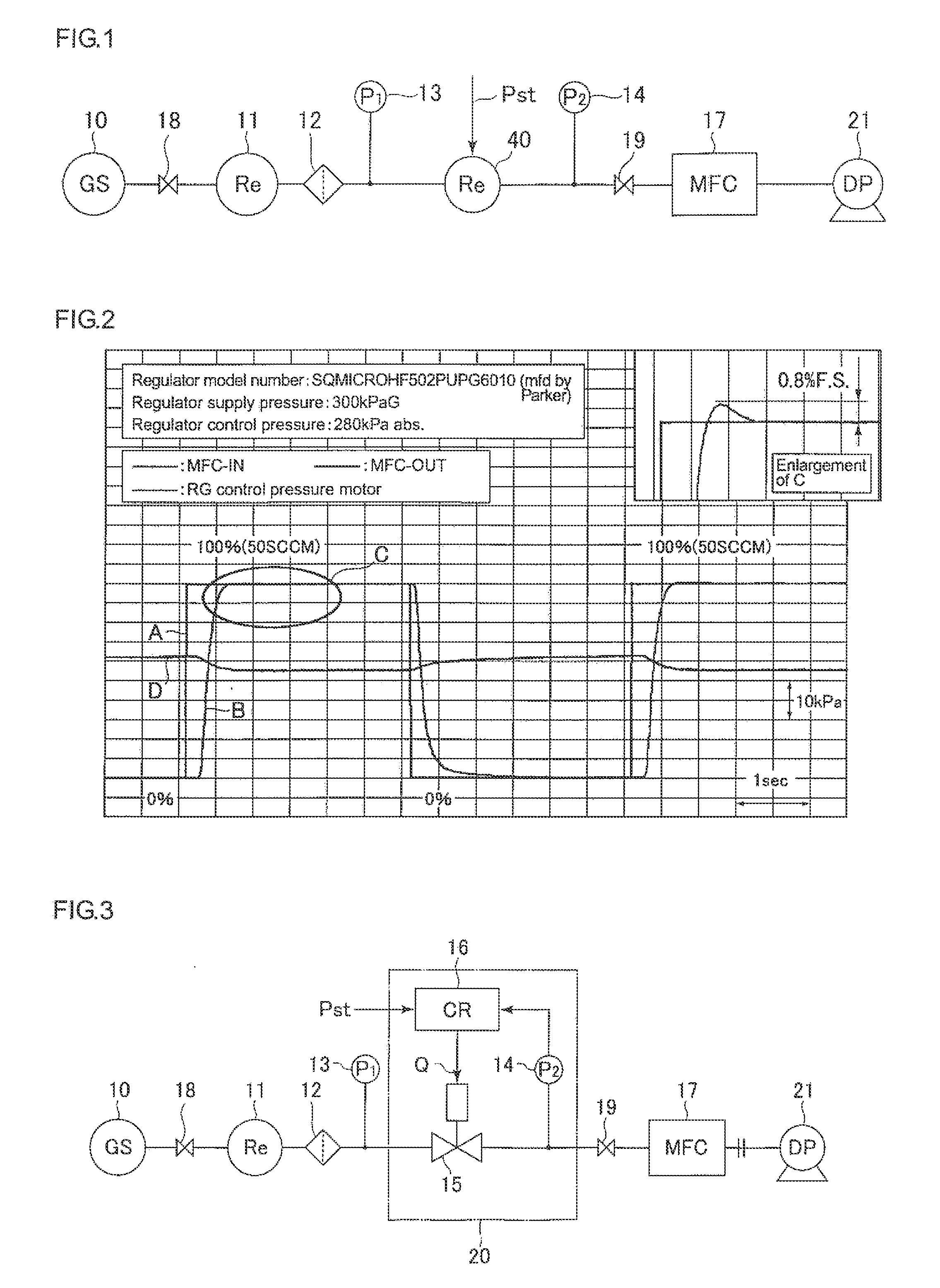
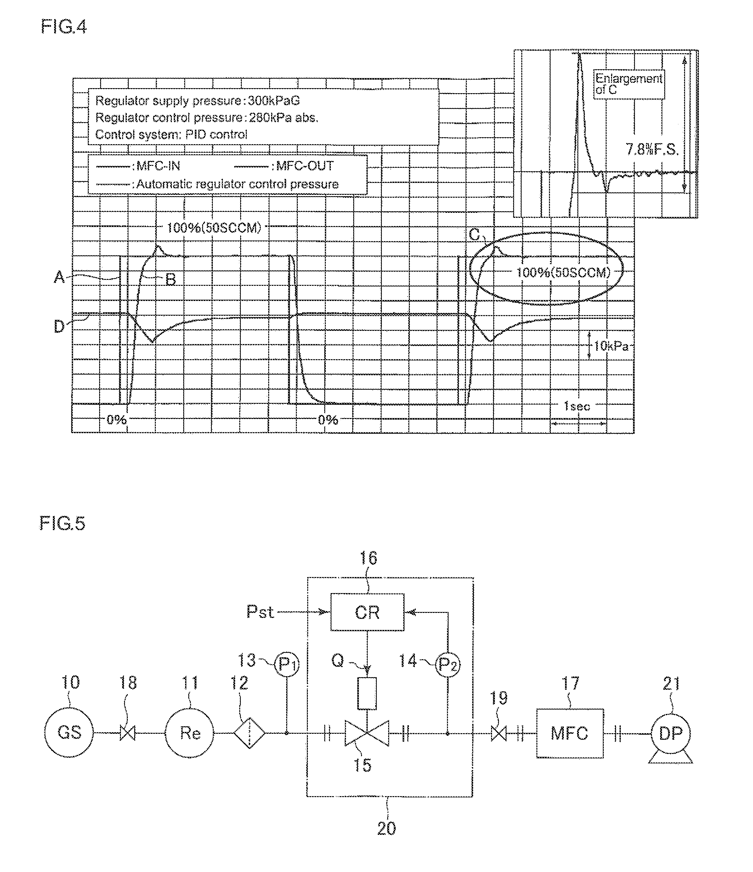
[0041]Hereinafter, an embodiment of the present invention will be described with reference to the drawings. FIG. 5 shows an apparatus embodiment of the present invention. Note that FIG. 5 is different from the apparatus of FIG. 3 with respect to the point that the thermal type mass flow rate regulator 17 used is set to be at a full-scale (F.S.) flow rate of 10 SCCM and 500 SCCM, and with respect to the point that the controller 16 is capable of selecting any one of a PID control action and a control action for bringing about a residual deviation in control pressure by disabling an integral action.

[0042]In addition, as is publicly known, the PID control action is a control system in which control deviation in control pressure of the pressure regulating valve 15 converges to zero eventually, and a control action, in which an integral action is disabled, is a control system in which control deviation does not become zero, but converges so as to have a certain deviation (offset). In oth...


PUM


Abstract

The invention prevents overshoot from occurring in flow rate on the output side of a flow rate regulator when output flow rate is changed or the gas type distributed is changed. Thus, an automatic pressure regulator is provided to supply gas pressure to a flow rate regulator that includes a piezoelectric element driving type pressure regulating valve, a control pressure detector provided on the output side of the pressure regulating valve, and a controller to which a detected value P2 of the control pressure detector and a set value Pst for control pressure are input, wherein the controller supplies a control signal to a piezoelectric element driving unit of the pressure regulating valve using a proportional control system to perform valve opening regulation, in which the proportional control system of the controller is set to control to bring about a residual deviation in control pressure by disabling an integral action.

Description

[0001]This is a National Phase Application in the United States of International Patent Application No. PCT / JP2009 / 001591 filed Jun. 4, 2009, which claims priority on Japanese Patent Application No. 2008-146498, filed Jun. 4, 2008. The entire disclosures of the above patent applications are hereby incorporated by reference. TECHNICAL FIELD OF THE INVENTION[0002]The present invention relates to an automatic pressure regulator for a flow rate regulator for a gas supply unit, which supplies gas to a chamber for semiconductor manufacturing, or the like. In particular, the present invention relates to an automatic pressure regulator for a flow rate regulator that is capable of almost entirely preventing overshoot from occurring in flow rate output of the flow rate regulator at the time of switching the supply gas flow rate, or the like.BACKGROUND OF THE INVENTION[0003]In a gas supply unit in a semiconductor manufacturing apparatus, or the like, as shown in FIG. 13, conventionally, a pres...

Claims


Application Information

Patent Timeline
IPC IPC(8): F16K31/02
CPCG05D7/0635Y10T137/7761
Inventor HIRATA, KAORUSUGITA, KATSUYUKINISHINO, KOUJIDOHI, RYOUSUKEIKEDA, NOBUKAZUSUGIMOTO, TAKEO
Owner FUJIKIN INC
Why Eureka
Try Eureka