Method for determining the sensitivity of an acceleration sensor or magnetic field sensor

Active Publication Date: 2011-06-16
ROBERT BOSCH GMBH
View PDF3 Cites 13 Cited by
  • Summary
  • Abstract
  • Description
  • Claims
  • Application Information

AI Technical Summary

Benefits of technology

[0028]The method according to the present invention has the advantage that it allows the sensitivity of a sensor to be determined and adjusted very precisely, in particular more precisely than with most methods currently known, without subjecting the sensor to external mechanical and/or magnetic stimulation. Thus, a complicated and therefore costly adjustment based on external mechanical or magnetic stimulation may advantageously be dispensed with and the adjustment operation may be simplified. In addition, the adjustment operation may be carried out largely independently of external interferenc

Problems solved by technology

Edge loss may result, for example, in reduced spring stiffness, seismic mass, and useful capacity for the capacitive evaluation.
For magnetic field sensors which measure a magnetic field component perpendicular to the substrate plane of the sensor (Bz elements), fluctuations in the edge loss essentially result in variation in the distances between the electrodes, an

Method used


Image

  • Method for determining the sensitivity of an acceleration sensor or magnetic field sensor
  • Method for determining the sensitivity of an acceleration sensor or magnetic field sensor
  • Method for determining the sensitivity of an acceleration sensor or magnetic field sensor

Examples


Example

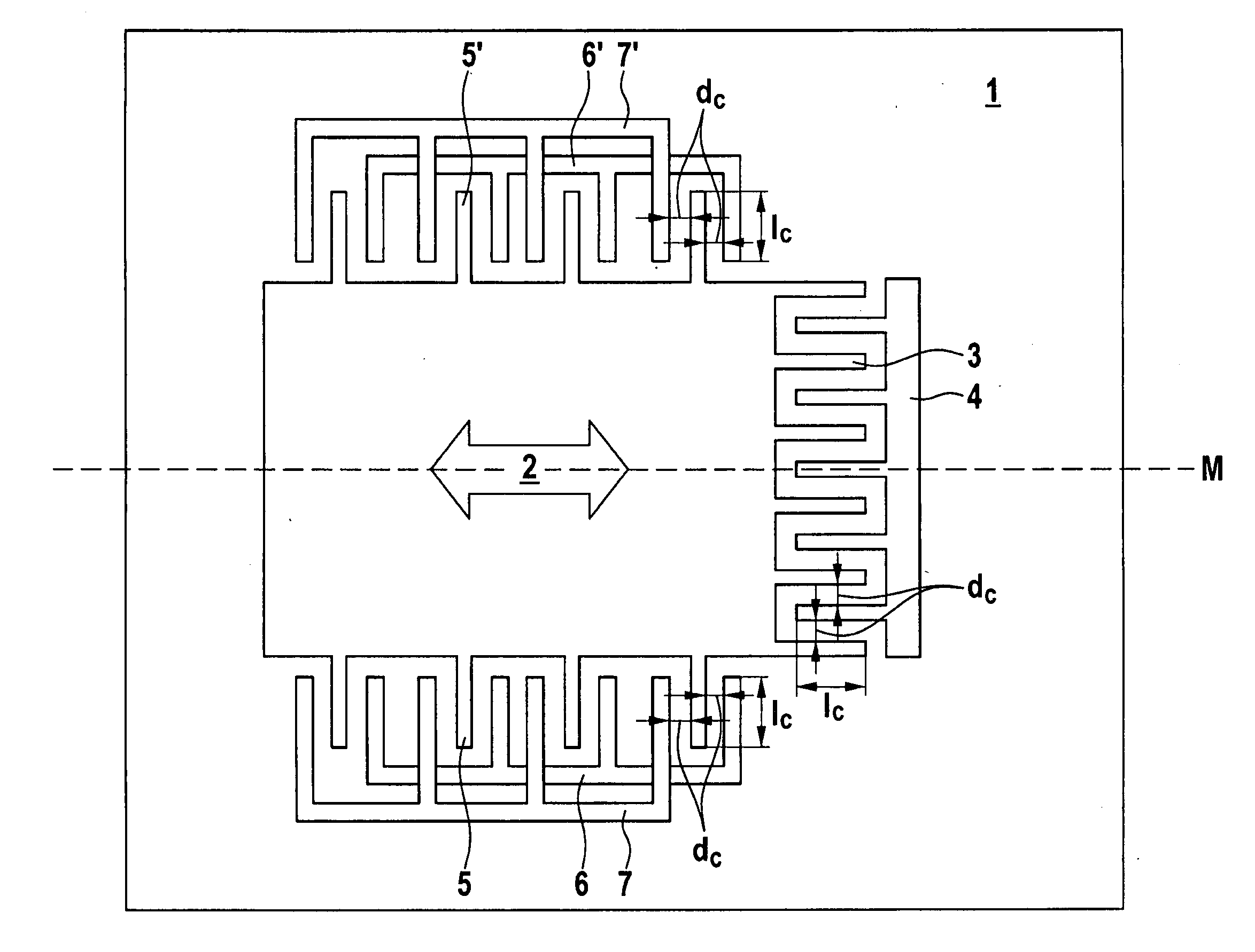
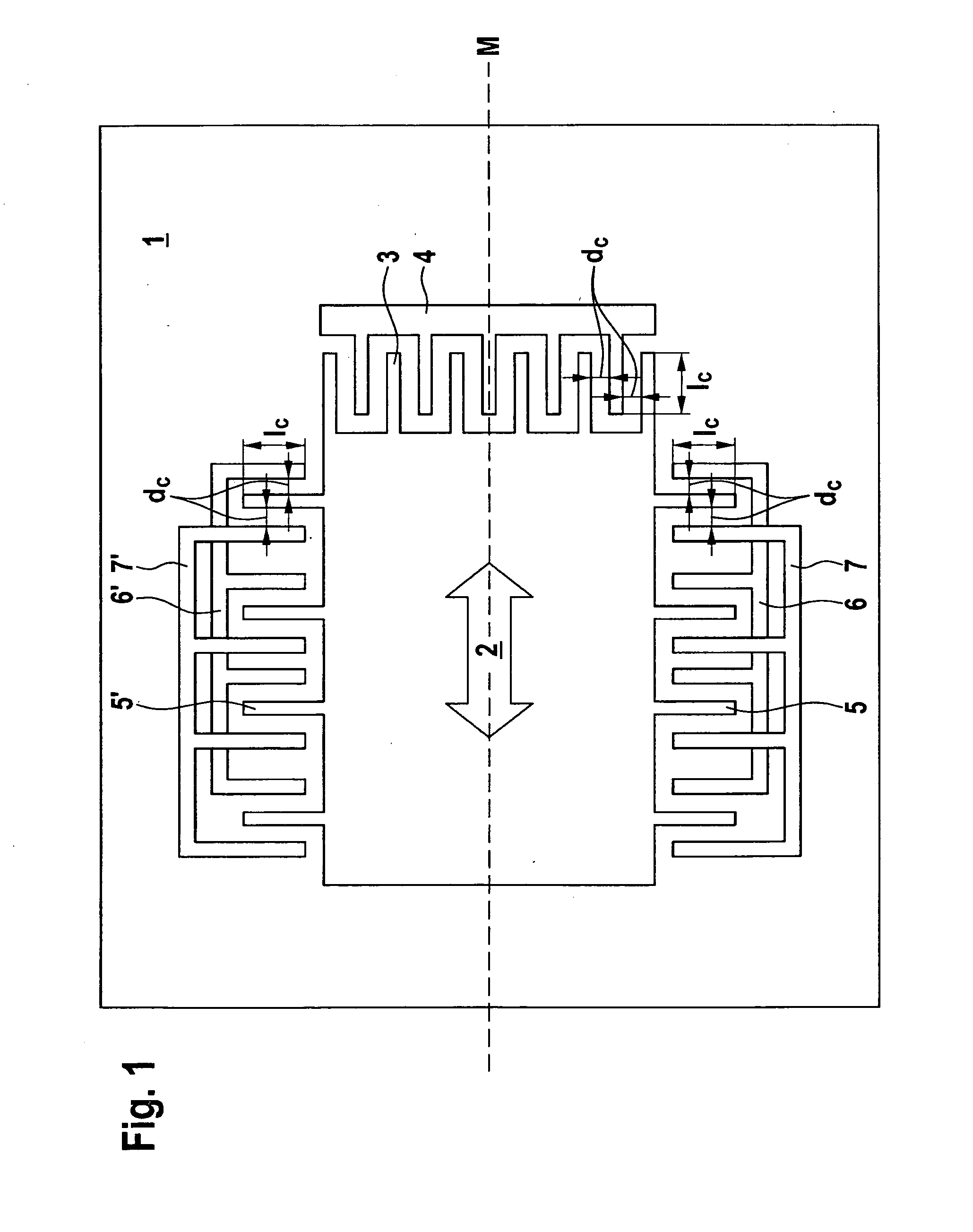
[0036]FIG. 1 shows that the sensor has a substrate 1, an elastically supported seismic mass 2 which is movable relative to substrate 1, and three electrode systems 3, 4; 5, 6, 7; 5′, 6′, 7′ for deflecting mass 2 relative to substrate 1 along measuring axis M. The springs for movably suspending mass 2 are not illustrated in FIG. 1. FIG. 1 shows that first electrode system 3, 4 is situated on a first side of mass 2, and second electrode system 5, 6, 7 is situated on a second side of mass 2. FIG. 1 also shows that a further electrode system 5′, 6′, 7′ is situated on the side of the mass located opposite the second side. However, according to the present invention no electrode system is provided on the side of mass 2 located opposite the first side. This has the advantage that the surface area of the sensor may be reduced.

[0037]FIG. 1 also shows that second electrode system 5, 6, 7 and further electrode system 5′, 6′, 7′ are capacitor electrode systems in which the distance between elec...


PUM


Abstract

A method for determining the sensitivity of a sensor provides the following steps: a) first and second deflection voltages are applied to first and second electrode systems of the sensor, respectively, and first and second electrostatic forces are exerted on an elastically suspended seismic mass of the sensor by the first and second electrode systems, respectively, and a restoring force is exerted on the mass as a result of the elasticity of the mass, and a force equilibrium is established among the first and second electrostatic forces and the restoring force, and the mass assumes a deflection position characteristic of the force equilibrium, and an output signal characteristic of the force equilibrium and of the deflection position is measured; and b) the sensitivity of the sensor is computed on the basis of the first and second deflection voltages.

Description

BACKGROUND OF THE INVENTION[0001]1. Field of the Invention[0002]The present invention relates to a method for determining the sensitivity of a sensor, e.g., an acceleration sensor or magnetic field sensor.[0003]2. Description of the Related Art[0004]Magnetic field sensors (magnetometers) are used as sensors for detecting the earth's magnetic field for compass applications. Microelectromechanical sensors (MEMS) are known which, using the Lorentz force, convert a magnetic field which is present to a mechanical deflection, and capacitively read out same. For this purpose, these sensors have electrical conductors which extend, at least in places, perpendicular to the magnetic field to be measured. Published German patent application document DE 198 27 056 A1 describes such a magnetic field sensor.[0005]In addition, acceleration sensors are known which are based on capacitively readable microelectromechanical systems (MEMS).[0006]The sensitivity of microelectromechanical sensors is based...

Claims


Application Information

Patent Timeline
IPC IPC(8): G01R33/02G01P15/105
CPCB81C99/003G01P15/125G01R33/0286G01P21/00G01P15/18
Inventor CLASSEN, JOHANNESKAELBERER, ARNDFAISST, HANS-JOERGFRANKE, AXELHATTASS, MIRKORANK, HOLGERSATTLER, ROBERTBUHMANN, ALEXANDERMAAS, RAMONAKECK, MARIAN
Owner ROBERT BOSCH GMBH
Why Eureka
Try Eureka