Screen unit

a screen unit and screen technology, applied in the field of screen units, can solve the problems of deteriorating the appearance of the screen in the expanded condition, increasing the size of the screen unit, and damage to the screen, so as to reduce the steps produced by the steps of the string-shaped members and reduce the deformation of the base material of the screen. the effect of the step reduction

Active Publication Date: 2011-06-16
SEIKO EPSON CORP
View PDF3 Cites 5 Cited by
  • Summary
  • Abstract
  • Description
  • Claims
  • Application Information

AI Technical Summary

Benefits of technology

[0011]According to this structure, the pair of string-shaped members are disposed between the winding shaft around which the screen is wound and the supporting portion. Thus, the respective string-shaped members as well as the screen are tensioned in the direction of winding the screen when the screen is expanded. The respective string-shaped members are provided outside the pair of crossing sides of the screen curved toward the inside along the respective crossing sides. Thus, the screen is also tensioned in the crossing direction which crosses the direction of winding the screen via the plural connecting members. Accordingly, winding curls and wrinkles in the vicinity of the crossing sides of the screen can be reduced, which increases the flatness of the screen.
[0012]Moreover, even when the respective string-shaped members wound around the winding shaft together with the screen overlap with the screen, contact between the string-shaped members and the base material of the screen can be avoided by the function of the cushioning members covering the string-shaped members and separating the string-shaped members from the screen. In this structure, the respective string-shaped members can be disposed closer to the corresponding crossing sides, and thus each length of the connecting members in the crossing direction can be reduced. Accordingly, size increase of the screen unit and deterioration of the appearance in the expanded condition of the screen can be reduced while preventing damage to the base material of the screen produced by the contact between the string-shaped members and the base material of the screen.Application Example 2
[0014]According to this structure, size increase of the screen unit and deterioration of the appearance in the expanded condition of the screen can be reduced while increasing the flatness of the screen and preventing damage to the base material of the screen produced by the contact between the string-shaped members and the base material of the screen.
[0015]In addition, according to this structure, the projection surface sides of the pair of the string-shaped members and the plural connecting members disposed on the respective crossing sides of the screen are covered by the cushioning members. In this case, the string-shaped members and the connecting members are not visually recognized from the projection surface side of the screen. Thus, the appearance of the screen unit in the expanded condition of the screen improves. Moreover, the cushioning members are disposed in the belt shapes in the directions substantially perpendicular to the first side and the second side extending approximately in parallel with each other. Thus, the shape of the screen exposed to the projection surface side becomes substantially rectangular. Accordingly, the images displayed on the projection surface of the screen are well defined, which improves the effect of appreciation of the images.Application Example 3
[0017]According to this structure, the thickness of each of the cushioning members is larger than the thickness of each of the string-shaped members. Thus, steps produced by the string-shaped members can be reduced within the range of the thickness of the cushioning members. Accordingly, deformations on the base material of the screen produced by the steps of the string-shaped members can be more effectively reduced.

Problems solved by technology

According to this screen unit, however, the screen is damaged by the contact between the string-shaped members provided along the curved crossing sides of the screen and the base material of the screen in the winding condition of the screen.
However, since the string-shaped members are disposed farther outward from the crossing sides of the screen, the size of the screen unit increases.
Moreover, the pipe-shaped members provided on both the crossing sides of the screen become longer in the crossing direction, which deteriorates the appearance of the screen in the expanded condition.

Method used


Image

  • Screen unit
  • Screen unit
  • Screen unit

Examples


first embodiment

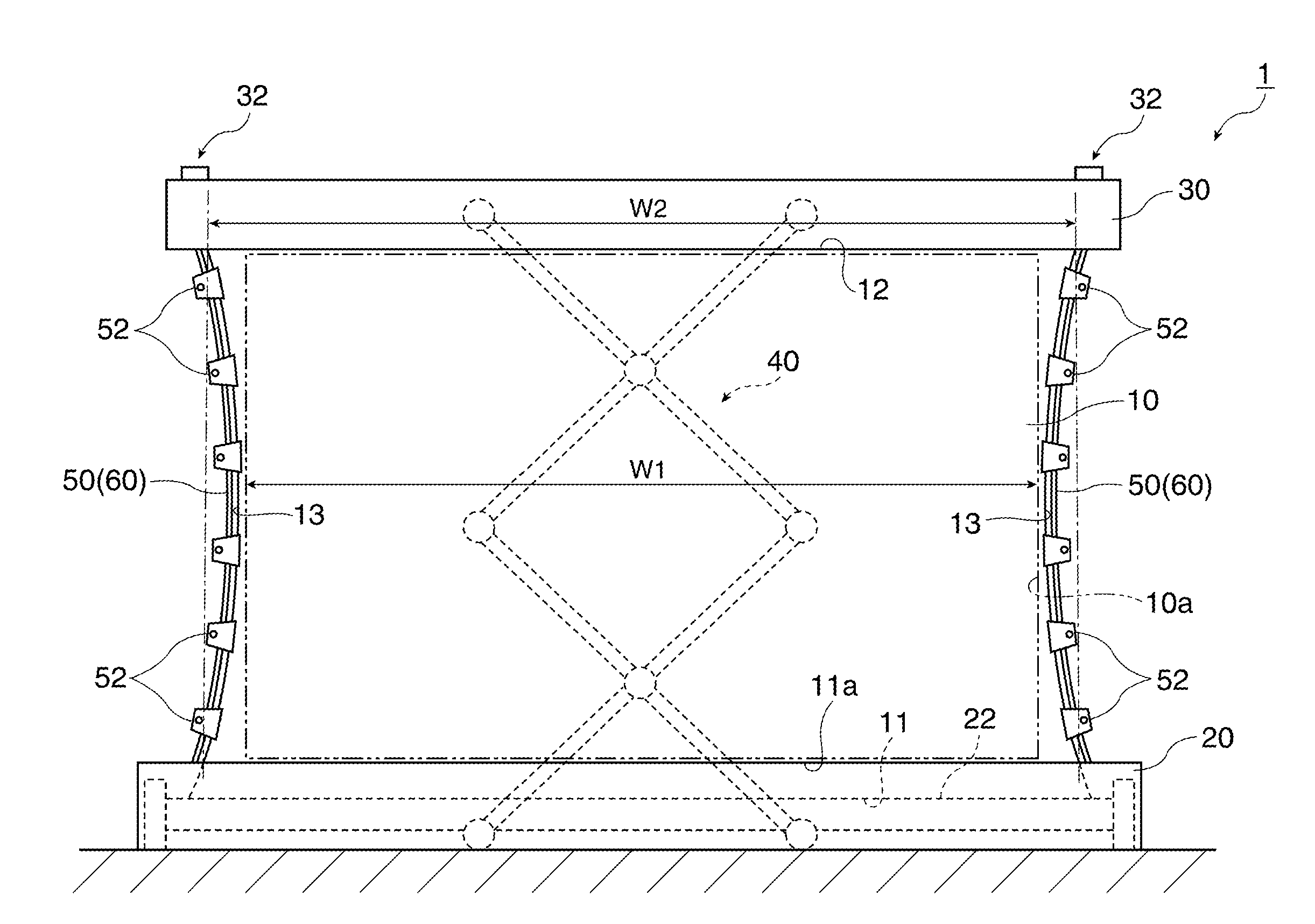
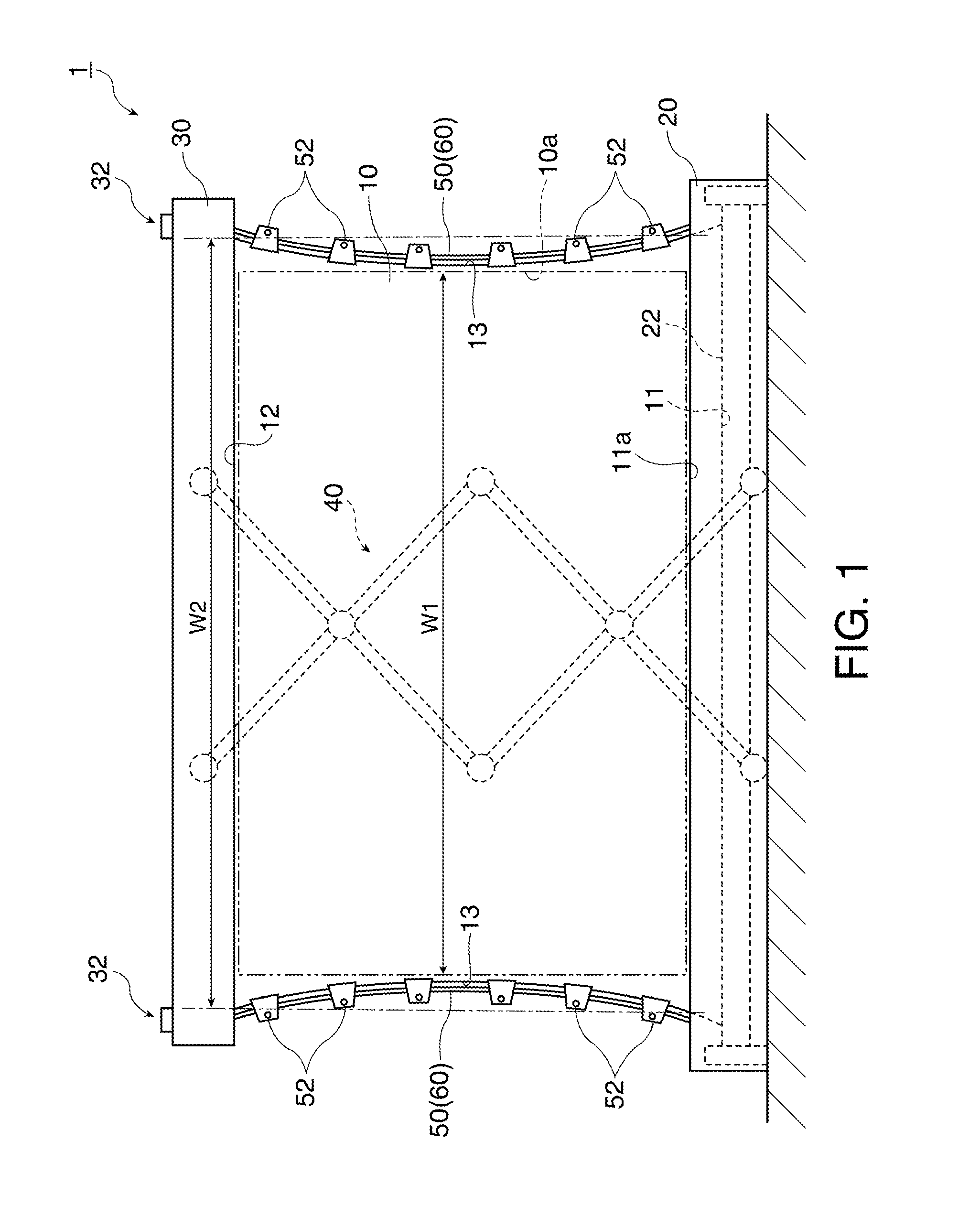
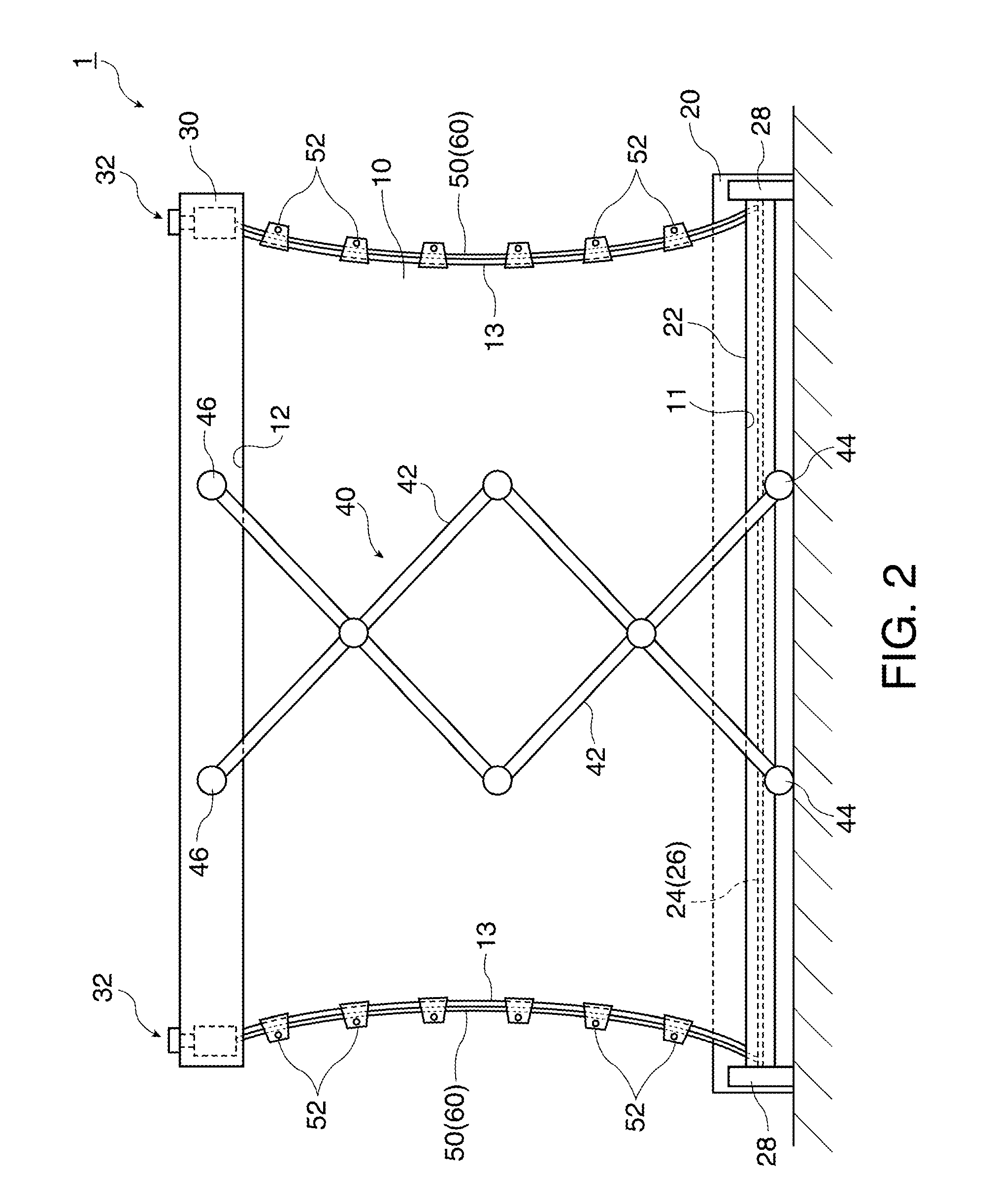
[0026]The general structure of a screen unit according to a first embodiment is now described. FIGS. 1 and 2 illustrate the general structure of the screen unit in the first embodiment. More specifically, FIG. 1 schematically illustrates the screen unit in the expanded condition as viewed from the front, and FIG. 2 schematically illustrates the screen unit in the expanded condition as viewed from the back. In FIG. 2, a storing portion 20 is shown in perspective.

[0027]FIG. 3 schematically illustrates ends of a wire and a winding shaft. FIG. 4 schematically illustrates a fixing portion of a supporting portion. FIG. 5 schematically illustrates an enlarged area around a connecting member. While each of FIGS. 3, 4, and 5 shows only one of both ends of the screen unit 1 in the left-right direction, the other end has the same structure as that shown in the figures.

[0028]As illustrated in FIG. 1, the screen unit 1 in the first embodiment includes a screen 10, the storing portion 20 having a...

second embodiment

[0064]A screen unit according to a second embodiment is now described with reference to the drawings. FIG. 6 illustrates the general structure of the screen unit in the second embodiment. More specifically, FIG. 6 schematically illustrates the screen unit in the expanded condition as viewed from the front.

[0065]The structure of the screen unit according to the second embodiment is similar to that of the screen unit in the first embodiment except for the construction and position of the cushioning members. The same reference numbers are given to components common to those in the first embodiment, and the explanation of the common components is not repeated.

[0066]As illustrated in FIG. 6, a screen unit 2 in the second embodiment includes the screen 10, the storing portion 20 having the winding shaft 22, the supporting portion 30, the coupling mechanism 40, a pair of the wires 50, the plural connecting members 52, and a pair of cushioning members 62.

[0067]The respective cushioning memb...

modified example 1

[0085]According to the screen unit 2 in the second embodiment, the cushioning members 62 are disposed on the front side of the screen 10. However, the cushioning members 62 may be provided on the back side of the screen 10, or on both the front side and the back side of the screen 10. The cushioning members 62 may be fixed to the wires 50 and the plural connecting members 52.


PUM


Abstract

A screen unit includes: a screen having a first side, a second side, and a pair of crossing sides which cross the first side and the second side; a winding shaft holding the first side and functioning as a shaft around which the screen is wound; a supporting portion supporting the second side; a pair of string-shaped members provided between the winding shaft and the supporting portion and disposed outside the pair of the crossing sides of the screen in the directions along the pair of the crossing sides; and a plurality of connecting members provided on the pair of the crossing sides to connect the screen and the pair of the string-shaped members, wherein the pair of the crossing sides are curved toward the inside of the screen, and cushioning members are provided in such a manner as to cover at least the pair of the string-shaped members.

Description

BACKGROUND[0001]1. Technical Field[0002]The present invention relates to a screen unit.[0003]2. Related Art[0004]A type of screen unit which expands a screen when the screen is used and winds and accommodates the screen when the screen is not used is known. An example of this type of screen unit currently proposed includes a screen which has a pair of crossing sides opposed in a direction crossing the winding direction of the screen (hereinafter referred to as a crossing direction as well) and curved toward the inside, pipe-shaped members provided on both the crossing sides, string-shaped members extended along the respective crossing sides and inserted into the pipe-shaped members, and a mechanism for giving tension to the respective string-shaped members in the directions along the respective crossing sides (for example, see JP-A-2009-229915).[0005]According to the structure of this screen unit which gives tension to the respective string-shaped members in the directions along the...

Claims


Application Information

Patent Timeline
Patent Type & Authority Applications(United States)
IPC IPC(8): G03B21/58G03B21/56H04N5/74
CPCG03B21/58
Inventor KUROI, KIYOSHI
Owner SEIKO EPSON CORP
Why Eureka
Try Eureka