
Harsh Environment Liquid Crystal Display (LCD) Enclosure

a liquid crystal display and enclosure technology, applied in the direction of electrical apparatus casings/cabinets/drawers, curtain suspension devices, revolving cabinets, etc., can solve the problems of compression depth, the seal quality of the hinge, and the display device is subject to breakag

Inactive Publication Date: 2011-06-16
CCS INC
View PDF29 Cites 59 Cited by
  • Summary
  • Abstract
  • Description
  • Claims
  • Application Information

AI Technical Summary

Benefits of technology

[0011]The numerous limitations inherent in the LCD enclosure systems described above provide great incentive for a new, better enclosure systems and methods capable of accounting for one or more of these issues. The present invention relates to a harsh environment LCD enclosure, and in particular, an enclosure that uses compound hinges providing two ranges of motion between the hinged elements (chassis and door), and uses a mounting system that allows for easy installation of, and access to, the enclosed LCD panel.
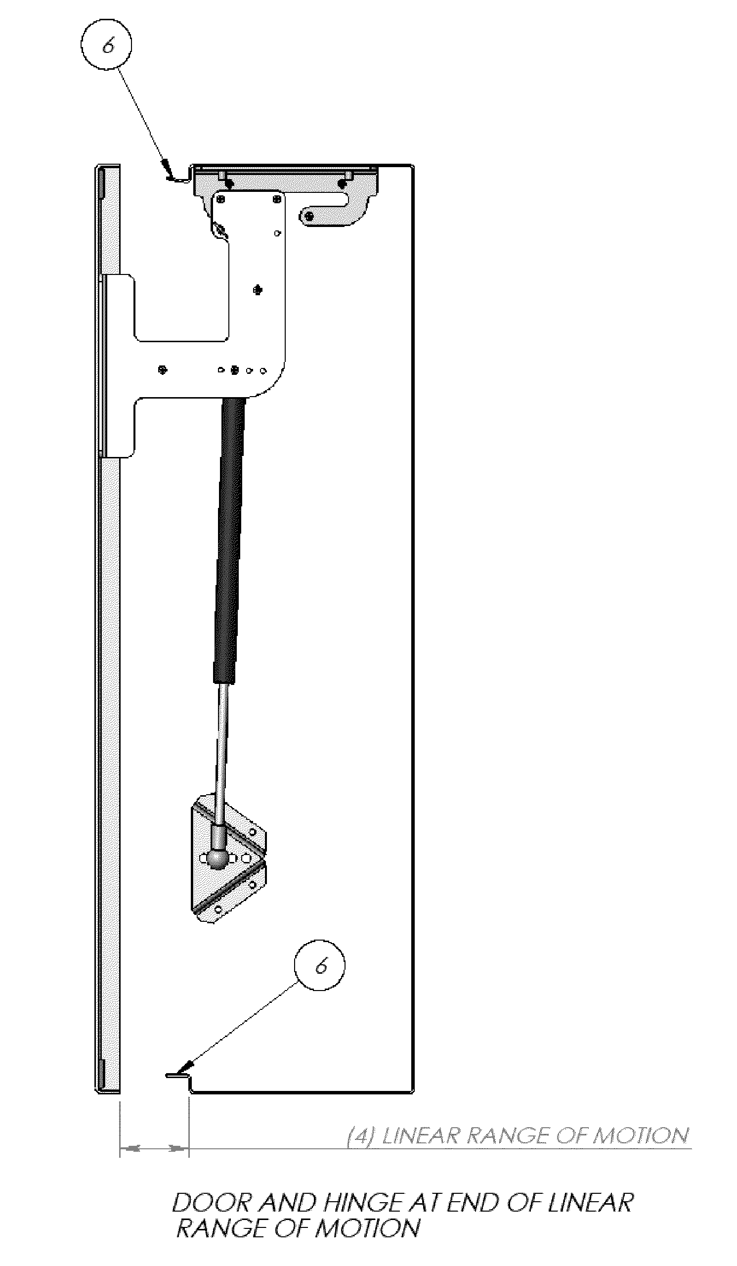
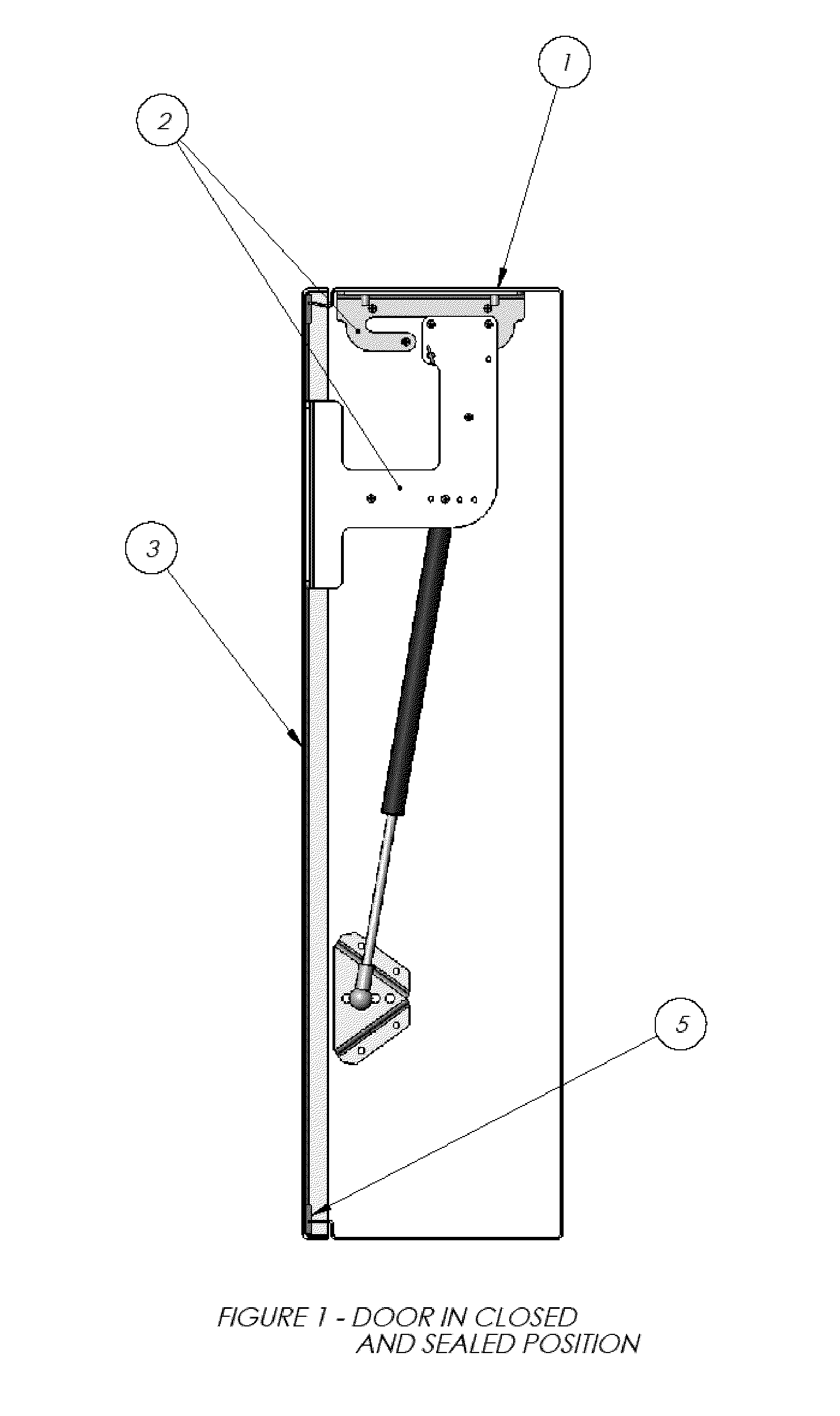
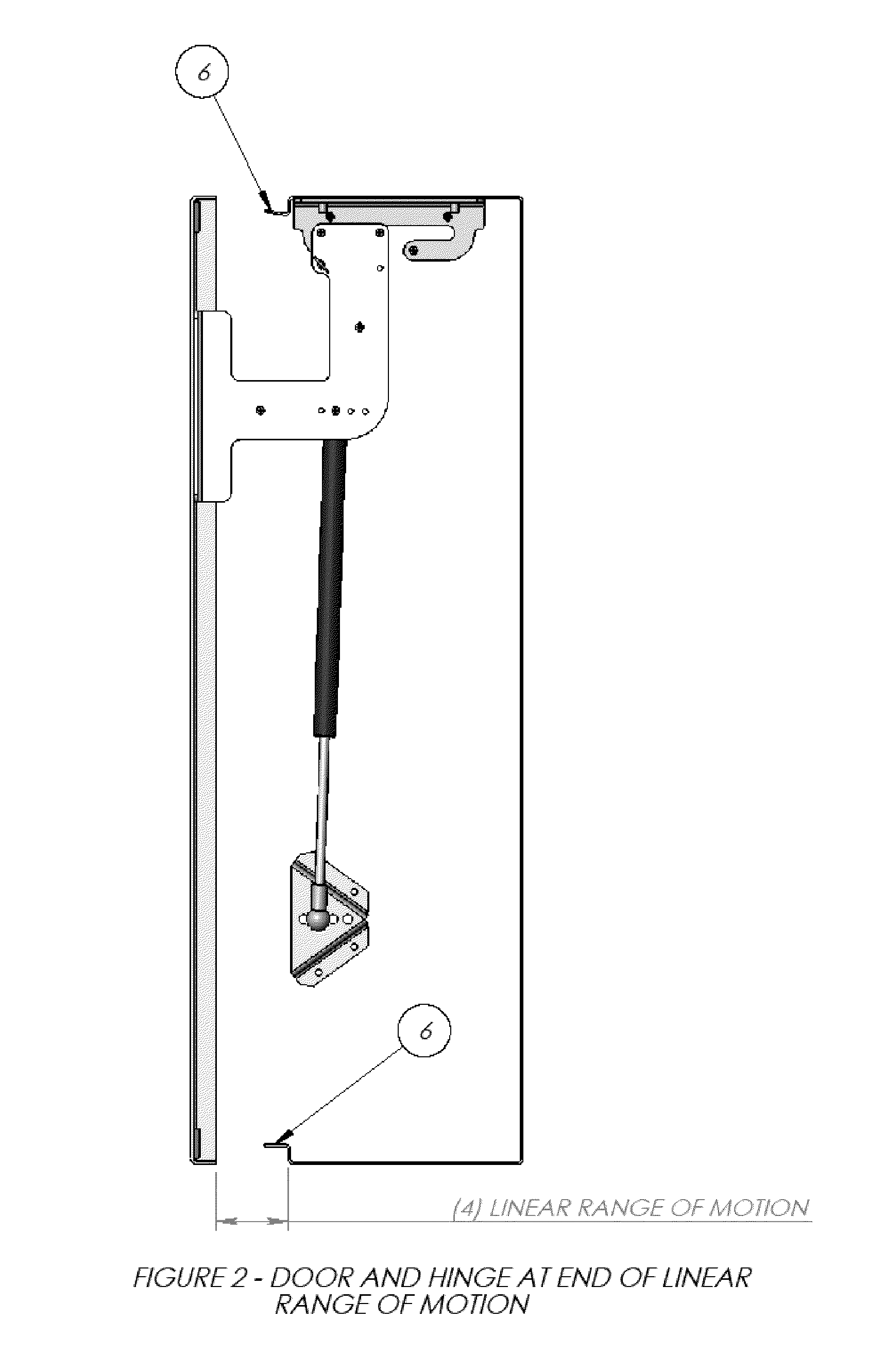
[0016]Some embodiments of the present invention provide a harsh environment LCD enclosure comprising: a casing with an interior for protecting an LCD panel; a door for accessing the interior of the casing; a compression gasket assembly for sealing together the door and casing; an actuator for opening and closing the door; and a hinge assembly disposed entirely within the interior of the casing and capable of providing for rotational and linear movement of the door relative to the casing.
[0018]Embodiments of the present invention provide a mounting system comprising: one or more mounting bars capable of being fixedly connected to a support surface and operatively configured to provide multiple mounting locations for bearing supports; one or more bearing supports capable of being fixedly connected to the mounting bars and operatively configured to provide a support for a hanger for an object; and a hanger for an object capable of being fixedly connected to an object and operatively configured for connection with the bearing supports in a manner to provide hanging support for the object, to provide rotational movement of the object relative to the mounting bar, and to provide for positioning of the object into one or more temporarily fixed positions away from the mounting bar.
[0019]The mounting system simplifies LCD panel mounting and provides an easy way to access the rear of the LCD panel and internal accessories without removing the LCD panel from the chassis. The mounting system uses LCD Supports and Bearing Supports to suspend the LCD from the top end of the panel while allowing the bottom end to rotate into and out of the enclosure chassis. When the panel is rotated out from the enclosure, prop arms can be leveraged downward to support the LCD in the extended position so maintenance can be performed on the interior of the enclosure chassis. When the panel is rotated into the enclosure, components of a latching system engage to lock the panel in place. With the latching system unlocked, the LCD panel can be disengaged from the upper Bearing Supports and removed from the chassis without tools or fasteners.
[0020]Of particular interest according to embodiments of the invention is a mounting system or assembly comprising: one or more mounting bars capable of being fixedly connected to a support surface and operatively configured to provide multiple mounting locations for bearing supports; one or more bearing supports capable of being fixedly connected to the mounting bars and operatively configured to provide a support for a hanger for an object; and a hanger for an object capable of being fixedly connected to an object and operatively configured for connection with the bearing supports in a manner to provide hanging support for the object, to provide rotational movement of the object relative to the mounting bar, and to provide for positioning of the object into one or more temporarily fixed positions away from the mounting bar. Optionally, the mounting bars and bearing supports or other components are universal to reduce complexity involved in manufacture / installation of the components.
[0021]For example, LCD panel mounting systems can include an upper and lower mounting bar (preferably arranged at a desired distance and parallel to one another), each supporting two identical bearing supports. Two object hangers with means for fixedly connecting the hangers to the back of an LCD panel and with means for quick engagement and disengagement of the hangers with the upper and lower bearing supports are included. A prop arm is included with one or both of the object hangers and is operatively configured to stow within the hanger when the hanger is closest to the upper and lower mounting bars and to be released into a position capable of propping the base of the hanger (and thus the LCD panel) a distance from the lower mounting bar. Optionally the mounting systems can comprise one or more quick-release latches for securing the hanger to the bearing supports. Such mounting systems can provide for easy and quick access to the area behind the LCD panel, especially for repairing or replacing equipment and / or equipment connections behind the installed LCD. In embodiments, the quick-release pulls do not require the use of tools to facilitate release.

Problems solved by technology

Conventionally, LCD display devices are subject to breakage due to collision or damage caused by exposure to a harsh working environment.
Hence, such types of LCDs are not suitable to operate in an outdoor environment.
Since the compression depth provided by a single axis hinge is not uniformly adjustable around the gasket perimeter, it has been found that variations in fabrication or assembly tolerances can alter the compression depth and thus the seal quality on the hinge side.
An additional issue with external exposed hinges is their aesthetic or obstructive impact, as some enclosure applications require a smooth exterior surface or streamlined shape.
With the LCD mounted in this fashion, any cabling or controls on the back of the LCD panel, or accessories located behind the LCD panel, are inaccessible until the LCD is unfastened and removed, making repairs or equipment exchange difficult and time consuming.
Therefore, despite improvements in LCD technology, there are still unmet needs such as those mentioned above for a new and improved LCD display enclosure.

Method used


Image

  • Harsh Environment Liquid Crystal Display (LCD) Enclosure
  • Harsh Environment Liquid Crystal Display (LCD) Enclosure
  • Harsh Environment Liquid Crystal Display (LCD) Enclosure

Examples


Embodiment Construction

[0050]In accordance with embodiments of the present invention, the present invention is directed to the field of environmentally sealed casings for protection of electronic or other devices. More particularly, the present invention relates to enclosures for protecting liquid crystal display (LCD) panels from the harsh environments in which they are sometimes used. One of the many potential advantages of the methods of the present invention, only some of which are discussed herein, is that the invention provides improved door operating systems that allow easy access to the interior space of such casings. Another advantage of the present invention includes the formation of a consistent and / or uniform seal between the door and the remainder of the protective chassis leading to better protection from the harsh environment. In certain embodiments, the present invention provides improved streamlined systems with a better, smoother look. Such a streamlined look may lead to more sales for s...


PUM


Abstract

The present invention is directed to the field of environmentally sealed casings for protection of electronic or other devices. More particularly, the present invention relates to enclosures for protecting LCD panels from the harsh environments in which they are sometimes used. In an embodiment, the present invention provides a harsh environment LCD enclosure comprising: a casing with an interior for protecting an LCD panel; a door for accessing the interior of the casing; a compression gasket assembly for sealing together the door and casing; an actuator for opening and closing the door; and a hinge assembly disposed entirely within the interior of the casing and operably configured to provide for rotational and linear movement of the door relative to the casing.

Description

CROSS-REFERENCE TO RELATED APPLICATIONS[0001]This application relies on the disclosure of and claims priority to and the benefit of the filing date of U.S. Provisional Application No. 61 / 285,441, filed on Dec. 10, 2009, which is hereby incorporated by reference herein in its entirety.BACKGROUND OF THE INVENTION[0002]1. Field of the Invention[0003]The present invention is directed to the field of environmentally sealed casings for protection of electronic or other devices. More particularly, the present invention relates to enclosures for protecting liquid crystal display (LCD) panels from the harsh environments in which they are sometimes used; door operating systems for accessing the interior space of such casings, which provide a consistent or uniform seal between the door and the remainder of the protective chassis; and systems for mounting electronic or other devices within such enclosures, which provide for quick and easy installation, removal, or rear access to such devices wi...

Claims


Application Information

Patent Timeline
IPC IPC(8): H05K7/00E05D11/04A47B96/00F16M13/00
CPCE05D3/022Y10T16/3828E05D11/06E05D15/56E05F1/1091E05Y2900/20E05Y2900/208F16M11/10F16M13/02F16M2200/024F16M2200/041A47B2220/0069Y10T16/5453Y10T16/364Y10T16/5406Y10T16/5377E05D5/065
Inventor FARLEY, JR., JAMES E.PEEPLES, WILLIAM A.
Owner CCS INC
Learn More