Planar light source module and optical film

a light source module and optical film technology, applied in the field of planar light source modules, can solve the problems of difficult reduction of fabrication costs and thickness of edge type backlight modules b>100/b>, and achieve the effect of high collimation

Inactive Publication Date: 2011-06-16
IND TECH RES INST
View PDF25 Cites 29 Cited by
  • Summary
  • Abstract
  • Description
  • Claims
  • Application Information

AI Technical Summary

Benefits of technology

[0011]The present application is directed to a planar light source module, and a planar light source provided by the planar light source module has a characteristic of high collimation.

Problems solved by technology

In the conventional edge type backlight module 100, since a large number of the optical films are used, a fabrication cost and a thickness of the edge type backlight module 100 are not easy to be reduced.
Although the aforementioned techniques can provide a highly collimated light source, they are not suitable for a mass production due to hard fabrication processes or complicated structures.

Method used


Image

  • Planar light source module and optical film
  • Planar light source module and optical film
  • Planar light source module and optical film

Examples


first embodiment

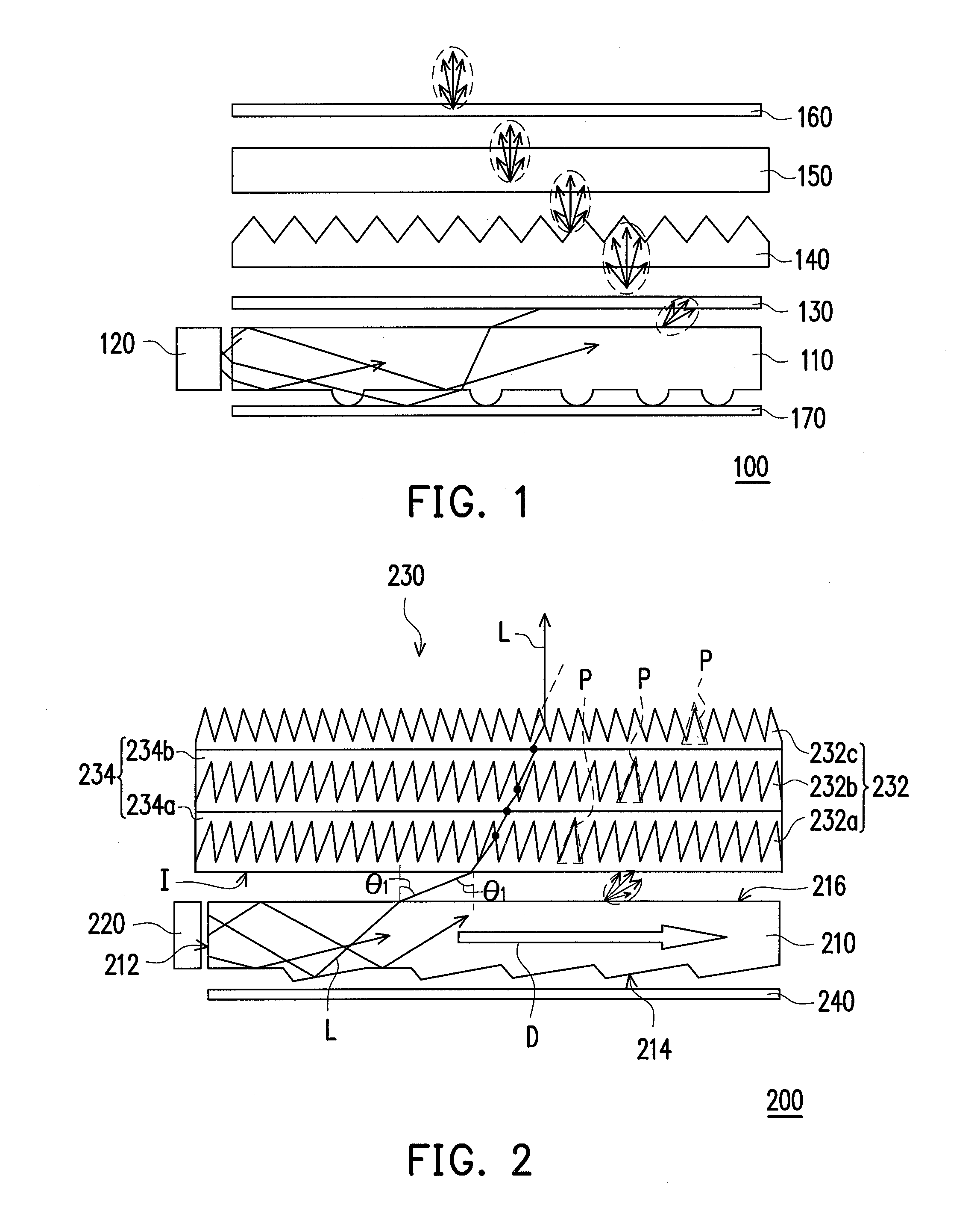
[0026]FIG. 2 is a schematic diagram illustrating a planar light source module according to the present application. Referring to FIG. 2, the planar light source module 200 of the present embodiment includes a light guide plate (LGP) 210, a light source 220, an optical film 230, and a reflector 240. The LGP 210 has a side light-incident surface 212, a bottom surface 214, and a light-emergence surface 216 opposite to the bottom surface 214. The LGP 210 of the present embodiment is, for example, a mirror dots LGP, a wedge-shaped LGP, a blasting spray LGP, or a LGP fabricated by a highly scattering optical transmission polymer (HSOT), etc.

[0027]The light source 220 is disposed adjacent to the side light-incident surface 212 of the LGP 210, and is suitable for providing a light beam L, wherein the light beam L enters the LGP 210 from the side light-incident surface 212 and leaves the LGP 210 from the light-emergence surface 216 in an emergence angle θ1, wherein the emergence angle θ1≧70 ...

second embodiment

[0037]FIGS. 7A and 7B are schematic diagrams illustrating a planar light source module according to the present application. Referring to FIG. 7A, to convert the light beam L into the TM mode polarized light before it enters the optical film 230, in the present embodiment, a polarizer PL1 can be disposed between the optical film 230 and the LGP 210. For example, the polarizer PL1 is, for example, a dual brightness enhancement film (DBEF) or a grating polarizer. Moreover, referring to FIG. 7B, the optical film 230 can also be directly fabricated on a polarizer PL2, and the prism layers 232a, 232b and 232c and the bonding layers 234a and 234b are alternately stacked on the polarizer PL2. Namely, the bottom surface (the surface close to the LGP 210) of the prism layer 232a is attached to the polarizer PL2, so as to integrate the optical film 230 and the polarizer PL2 into one optical device. Similarly, the polarizer PL2 is, for example, a DBEF or a grating polarizer.

[0038]According to...


PUM


Abstract

A planar light source module including a light guide plate (LGP), a light source, an optical film, and a reflector is provided. The light source for emitting a light beam is disposed adjacent to the side light-incident surface, wherein the light beam enters the LGP from a side light-incident surface and leaves the LGP from a light-emergence surface in an emergence angle θ1, θ1≧70 degrees. The optical film is disposed above the LGP to collimate the light beam from the LGP. The optical film includes a prism layer module and a bonding layer module stacked alternately. The prism layer module comprises prism layers and each prism layer includes micro-prisms. The bonding layer module comprises at least one bonding layer bonded with two prism layers adjacent thereto. The refraction index of the prism layers is greater than that of the bonding layer. The reflector is disposed under the bottom surface.

Description

CROSS-REFERENCE TO RELATED APPLICATION[0001]This application claims the priority benefit of Taiwan application serial no. 98142979, filed on Dec. 15, 2009. The entirety of the above-mentioned patent application is hereby incorporated by reference herein and made a part of this specification.BACKGROUND OF THE INVENTION[0002]1. Field of the Invention[0003]The present application relates to a planar light source module. More particularly, the present application relates to a highly collimated planar light source module.[0004]2. Description of Related Art[0005]Presently, liquid crystal display (LCD) becomes one of the most popular industries, the LCDs are widely used in mobile phones, personal digital assistants (PDA), car monitors, screens of notebook computers, screens of desktop computers, and LCD-TVs, etc. Since a thin-film transistor LCD is a non-emission display, besides a LCD panel for displaying images is used, an additional backlight module is required for providing a planar li...

Claims


Application Information

Patent Timeline
Patent Type & Authority Applications(United States)
IPC IPC(8): F21V13/00G02B5/30
CPCG02B5/045
Inventor CHANG, YEM-YEUTING, CHIA-JEN
Owner IND TECH RES INST
Why Eureka
Try Eureka