Method for detecting an ingress of a short-wave radio signal in a power line communication system and power line communication modem

Active Publication Date: 2011-06-16
SONY CORP
View PDF9 Cites 11 Cited by
  • Summary
  • Abstract
  • Description
  • Claims
  • Application Information

AI Technical Summary

Benefits of technology

[0006]It is an object of the invention to provide a method for detecting an ingress of a short wave

Problems solved by technology

Fixed radio broadcasting or other external transmissions

Method used


Image

  • Method for detecting an ingress of a short-wave radio signal in a power line communication system and power line communication modem
  • Method for detecting an ingress of a short-wave radio signal in a power line communication system and power line communication modem
  • Method for detecting an ingress of a short-wave radio signal in a power line communication system and power line communication modem

Examples


Example

[0015]In the following, embodiments of the invention are described. It is important to note that all described embodiments in the following may be combined in any way, i.e. there is no limitation that certain described embodiments may not be combined with others. Further, it should be noted that same reference signs throughout the Figures denote same or similar elements.

[0016]It is to be understood that other embodiments may be utilized and structural or logical changes may be made without departing from the scope of the invention. The following detailed description, therefore, is not to be taken in a limiting sense, and the scope of the present invention is defined by the appended claims.

[0017]It is to be understood that the features of the various embodiment described herein may be combined with each other, unless specifically noted otherwise.

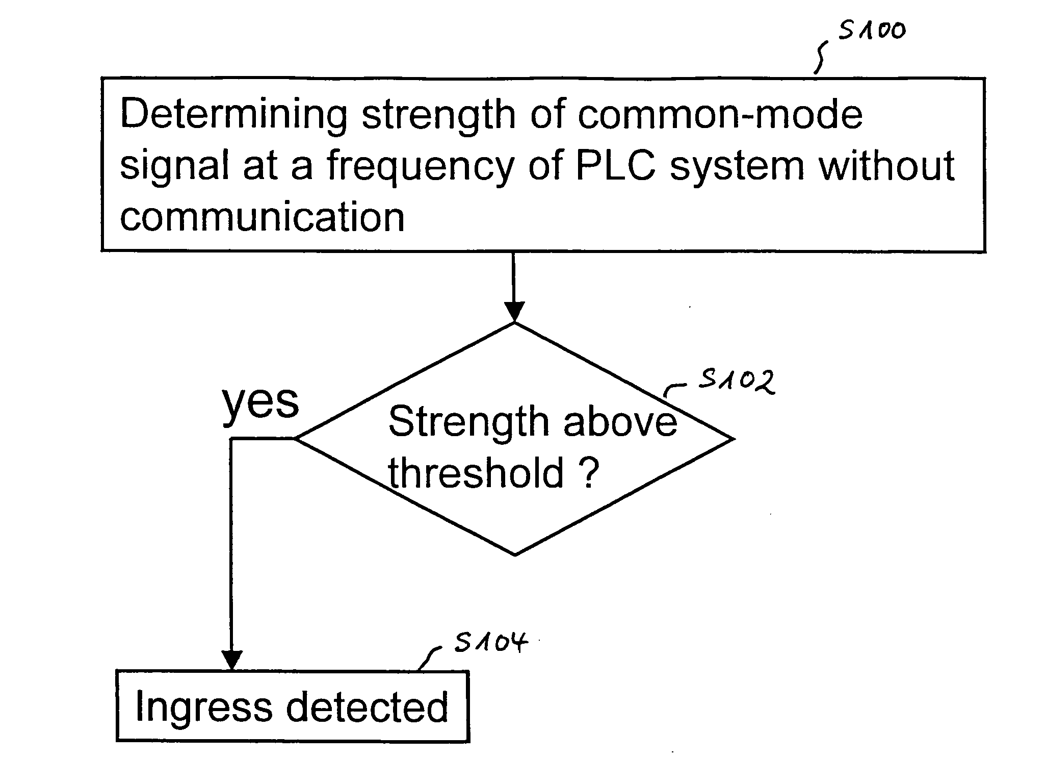
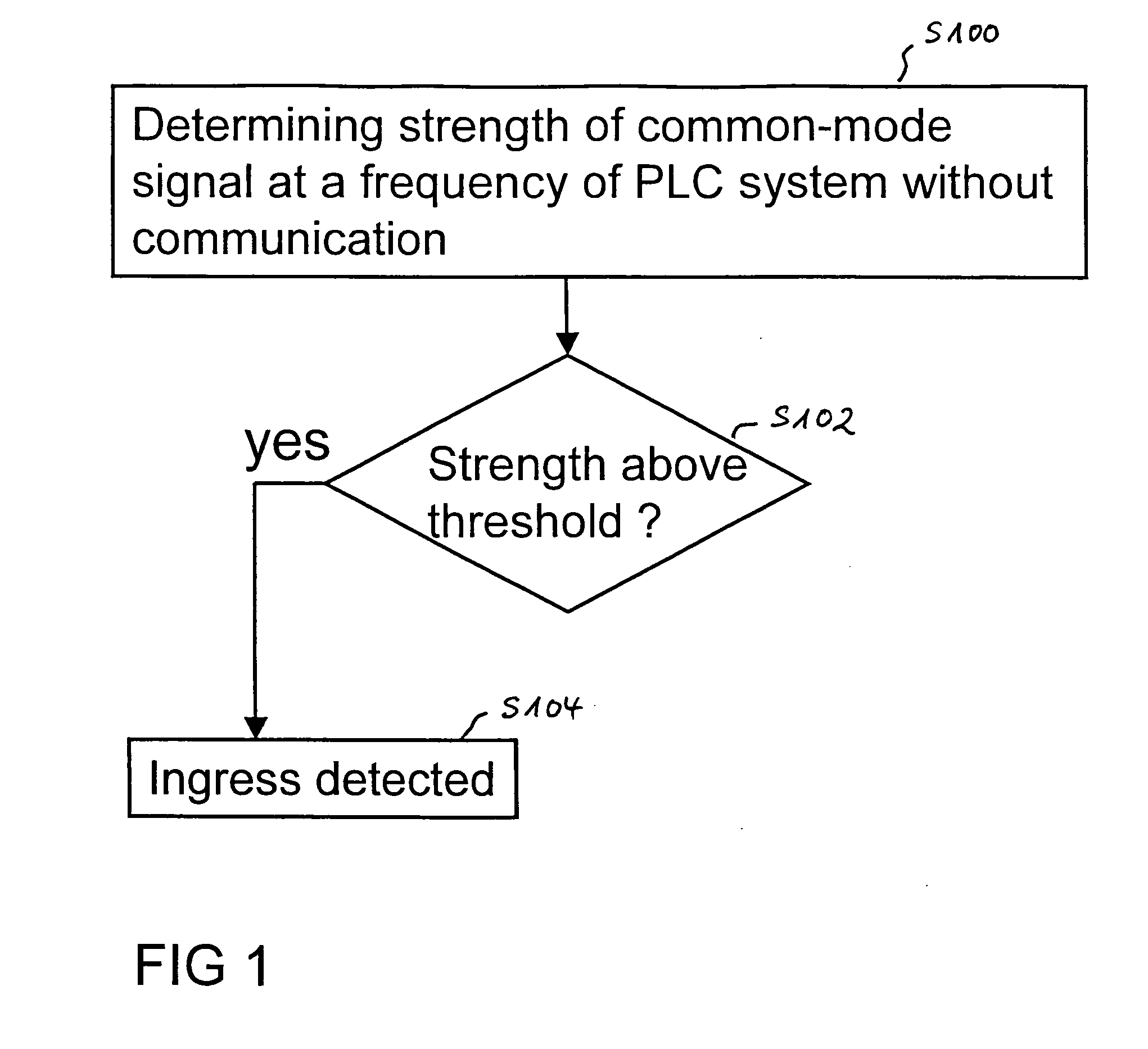
[0018]In FIG. 1 a schematic flowchart of a method for detecting an ingress of the short wave radio signal in a power line communication is d...


PUM


Abstract

A method for detecting an ingress of a short wave radio signal in a power line communication system which determines a strength of a common mode signal at a frequency of the power line communication system during a time period when no communication in the power line communication system at this frequency takes place and an ingress is detected if the strength of the common mode signal is above a determined threshold. A corresponding power line communication modem can implement such a method.

Description

[0001]An embodiment of the invention relates to a method for detecting an ingress of a short wave radio signal in a power line communication system. A further embodiment of the invention relates to a power line communication modem.BACKGROUND[0002]Power line communication (PLC), also called mains communication, power line transmission or power line telecommunication (PLT), broadband power line (BPL), power band or power line networking (PLN) is a term describing several different systems for using power distribution wires for simultaneous distribution of data. A carrier can communicate voice and data by superimposing an analog signal of a standard 50 or 60 Hz alternating current (AC). For indoor applications, PLC equipment can use household electrical power wiring as a transmission medium. This is a technique used e.g. for home networking or in home automation for remote control of lighting and appliances without installation of additional wiring.[0003]In standard PLC systems the sig...

Claims


Application Information

Patent Timeline
IPC IPC(8): H04B3/54H04B17/00H04B1/38
CPCH04B3/54H04B2203/5495H04B2203/5466H04B3/32
Inventor SCHWAGER, ANDREAS
Owner SONY CORP
Why Eureka
Try Eureka