Method and Apparatus for Acquiring Accurate Background Infrared Signature Data on Moving Targets

a technology for infrared signature data and moving targets, applied in direction finders, optical radiation measurement, instruments, etc., can solve the problems of low ir signatures of modern military aircraft, especially rotorcraft, a major measurement challenge, noisy and irreproducible ir signature measurement results, etc. problem

Active Publication Date: 2011-06-16
TEXTRON INNOVATIONS
View PDF11 Cites 6 Cited by
  • Summary
  • Abstract
  • Description
  • Claims
  • Application Information

AI Technical Summary

Problems solved by technology

Infrared (IR) signature measurements of military aircraft are needed to assess vulnerability to IR missiles and to evaluate efforts to reduce this vulnerability; however, the low IR signatures of modern military aircraft, especially rotorcraft, present a major measurement challenge.
IR signature measurement results are often very noisy and irreproducible.
The main problem with this technique is that the background data is only valid for the final scene of the target measurement.

Method used


Image

  • Method and Apparatus for Acquiring Accurate Background Infrared Signature Data on Moving Targets
  • Method and Apparatus for Acquiring Accurate Background Infrared Signature Data on Moving Targets

Examples


Embodiment Construction

[0011]Illustrative embodiments of the invention are described below. In the interest of clarity, not all features of an actual implementation are described in this specification. It will of course be appreciated that in the development of any such actual embodiment, numerous implementation-specific decisions must be made to achieve the developer's specific goals, such as compliance with system-related and business-related constraints, which will vary from one implementation to another. Moreover, it will be appreciated that such a development effort might be complex and time-consuming but would nevertheless be a routine undertaking for those of ordinary skill in the art having the benefit of this disclosure.

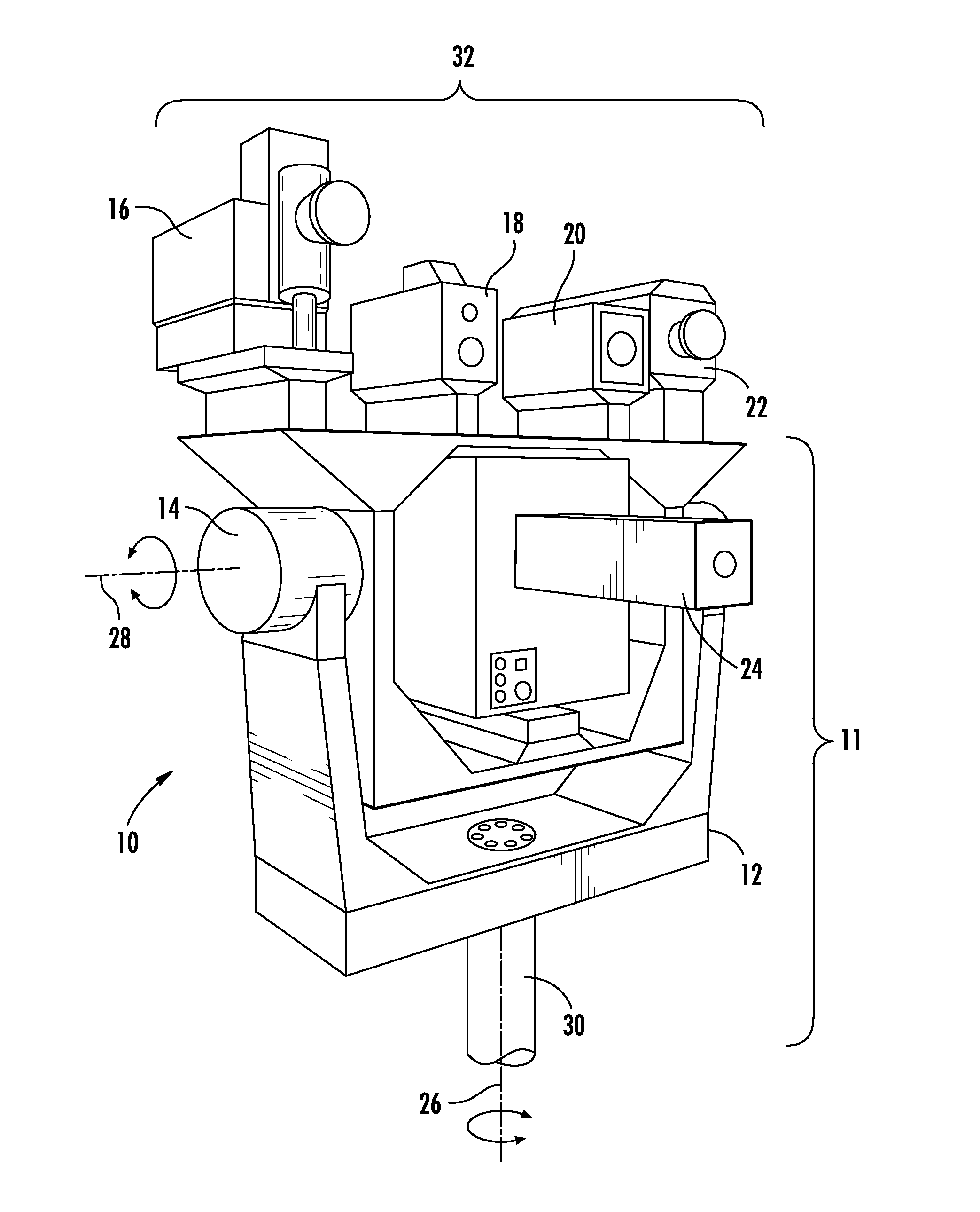
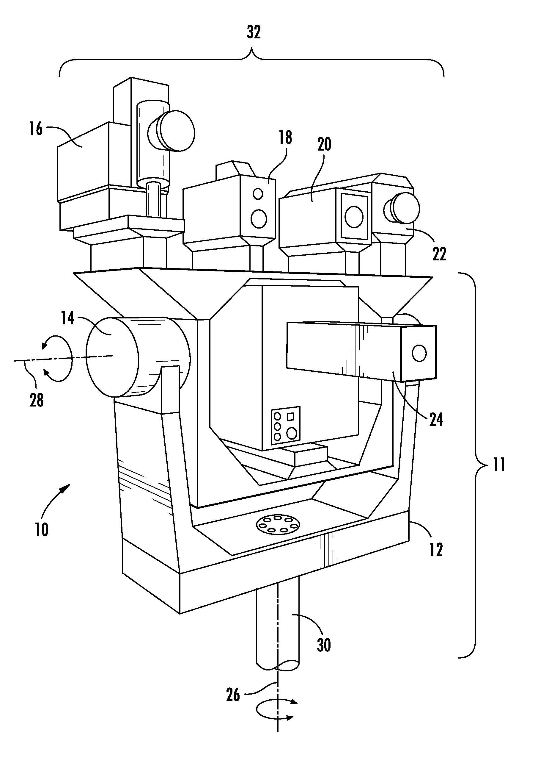
[0012]Referring to FIG. 1 in the drawings, a perspective view of the preferred embodiment of a tracker system 10 according to the present application is illustrated. Tracker system 10 preferably comprises a pan-and-tilt tracker platform 12 and a tracker assembly 32. Tracker platfo...


PUM


Abstract

A method for measuring an infrared signature of a moving target includes: tracking the moving target with a tracking system along a path from a start position to an end position, measuring infrared radiation data of the moving target along the path, repositioning the tracking system to the start position, retracing the path to measure the infrared radiation data of the background, and determining the infrared signature of the moving target by comparing the infrared radiation data of the moving object with the infrared radiation data of the background without the moving object.

Description

TECHNICAL FIELD[0001]The present invention relates to systems for tracking the infrared signatures of moving targets.DESCRIPTION OF THE PRIOR ART[0002]The phrase “infrared signature” is often used by defense scientists and military personnel to describe the appearance of objects to infrared sensors. An infrared signature depends on many factors, including the shape and size of the object, temperature and emissivity, the background against which the object is viewed, and the waveband of the detecting sensor. For example, the infrared signature of a truck viewed against a field will vary significantly with changing weather, time of day, and engine loading.[0003]There are two main purposes for studying infrared signatures: one is to understand the likely infrared signature of certain threats, so that equipment can be developed to detect the threats; and the second, to reduce the infrared signature of one's own assets to opposing threat sensors. In practice, this might mean equipping a ...

Claims


Application Information

Patent Timeline
Patent Type & Authority Applications(United States)
IPC IPC(8): G06K9/00G01J5/52
CPCF41G3/14G01S3/7864G01S3/7803F41G3/22
Inventor SHEPHERD, ROBERT A.SCHLICHTE, DAVID R.SHEPHERD, RICHARD A.GOODMAN, KENDALL E.
Owner TEXTRON INNOVATIONS
Why Eureka
Try Eureka