Conical friction ring type continuously variable transmission device

a transmission device and friction ring technology, applied in the direction of gearing, gearing elements, hoisting equipment, etc., can solve the problems of large size of the oil guide itself, reduced transmission efficiency, cost and installation space, etc., and achieves reliable transmission, low cost and installation space. , the effect of large shear resistan

Inactive Publication Date: 2011-06-16
AISIN AW CO LTD
View PDF0 Cites 5 Cited by
  • Summary
  • Abstract
  • Description
  • Claims
  • Application Information

AI Technical Summary

Benefits of technology

[0008]The oil guide provided substantially over the entire axial length comes with disadvantages in terms of the large size of the oil guide itself, as well as in terms of cost and installation space. In addition, the input-side friction wheel and the output-side friction wheel are dipped in the oil reservoir and experience rotational resistance due to the oil. In the case of friction oil in particular, the rotation of the friction wheels causes the friction oil to generate a large shear force, which may lower transmission efficiency.
[0017]According to a seventh aspect of the present invention, a traction oil is provided interposed between the contact surfaces of the conical friction wheel and the ring, and torque can be reliably transferred through a shear force of the traction oil in an extreme pressure condition. Once a rotation member is dipped in the traction oil, a large shear resistance is generated between the rotation member and the traction oil. However, the portion of the rotation member submerged in the traction oil is minimized to an axial portion on the large diameter side of the first conical friction wheel on the outside of the ring. Therefore, there is little power loss due to oil resistance.

Problems solved by technology

The oil guide provided substantially over the entire axial length comes with disadvantages in terms of the large size of the oil guide itself, as well as in terms of cost and installation space.
In the case of friction oil in particular, the rotation of the friction wheels causes the friction oil to generate a large shear force, which may lower transmission efficiency.

Method used


Image

  • Conical friction ring type continuously variable transmission device
  • Conical friction ring type continuously variable transmission device
  • Conical friction ring type continuously variable transmission device

Examples


Embodiment Construction

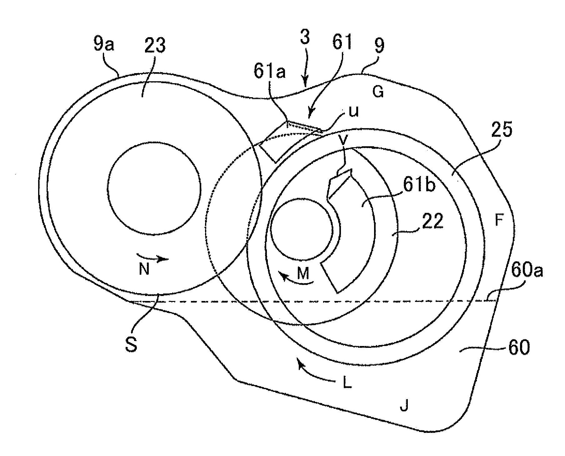
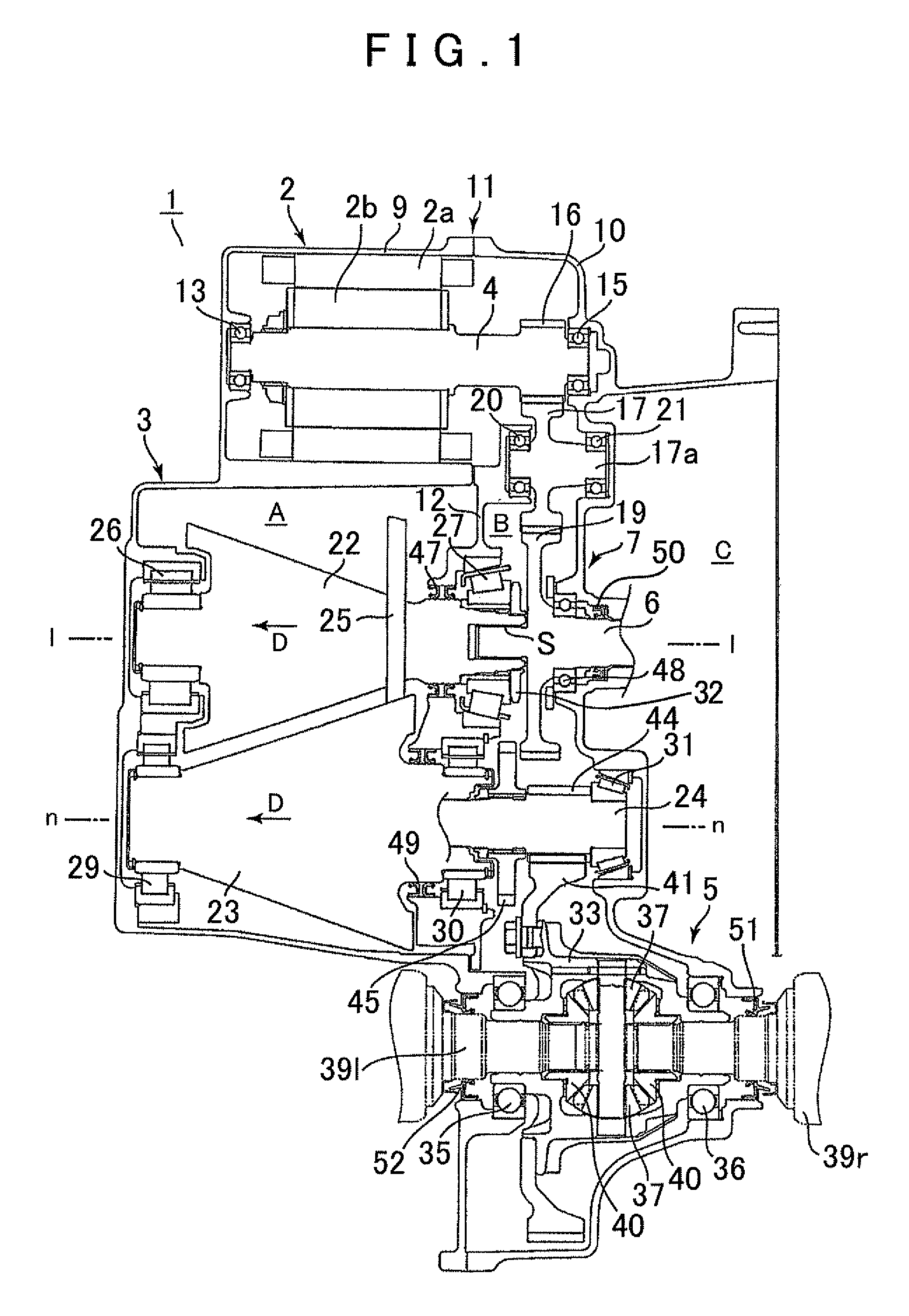
[0021]A hybrid drive system to which the present invention is applied will be described below with reference to the attached drawings. As shown in FIG. 1, a hybrid drive system 1 includes an electric motor 2, a cone ring type continuously variable transmission device (a conical friction ring type continuously variable transmission device) 3, a differential device 5, an input shaft 6 that moves in accordance with an output shaft of an engine (not shown), and a gear transmission device 7. The above devices and shafts are housed in a case 11 that is formed by two case members, that is, a case member 9 and a case member 10. Further, the case 11 includes a first space A and a second space B divided by a partition 12 in an oil-tight manner.

[0022]The electric motor 2 includes a stator 2a fixed to the first case member 9, and a rotor 2b provided on an output shaft 4. A first-side end portion of the output shaft 4 is rotatably supported by the first case member 9 through a bearing 13, and a ...


PUM


Abstract

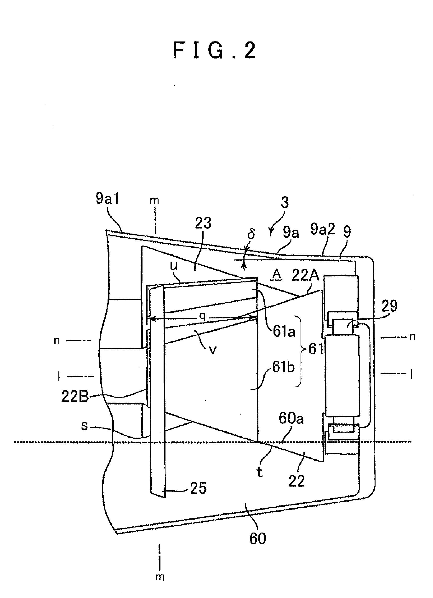
A conical friction ring type continuously variable transmission device configured a ring is provided such that it is interposed between opposing inclined surfaces of a first and second conical friction wheels so as to surround the first conical friction wheel. In this configuration, power is transmitted by contact between the ring and the first and second conical friction wheels, which moves the ring in the axial direction to steplessly change speed. A portion of the ring is submerged in an oil reservoir in a lower portion of the space when the ring is moved to any position in the axial direction. An oil guide is disposed on an axial partial region on the small diameter side of the first conical friction wheel, and guides oil raked up from the oil reservoir due to the rotation of the ring toward the first conical friction wheel.

Description

INCORPORATION BY REFERENCE[0001]The disclosure of Japanese Patent Application No. 2009-280744 filed on Dec. 10, 2009 including the specification, drawings and abstract is incorporated herein by reference in its entirety.BACKGROUND OF THE INVENTION[0002]The present invention relates to a conical friction ring type continuously variable transmission device that has a pair of conical friction wheels disposed mutually parallel and disposed such that a large diameter side and a small diameter side are opposite each other in an axial direction; and a ring that is provided interposed between opposing inclined surfaces of the friction wheels, wherein the ring is moved in the axial direction to steplessly change a speed. More specifically, the present invention relates to an oil guide structure that guides oil to the conical friction wheels.DESCRIPTION OF THE RELATED ART[0003]A known conical friction ring type continuously variable transmission device (also called a cone ring type continuous...

Claims


Application Information

Patent Timeline
Patent Type & Authority Applications(United States)
IPC IPC(8): F16H15/04
CPCF16H15/42F16H57/0457F16H57/0491
Inventor YAMASHITA, MITSUGITAKAHASHI, SHOJIUMEDA, HIDEYUKI
Owner AISIN AW CO LTD
Why Eureka
Try Eureka