Drive unit and control apparatus thereof

a technology of drive unit and control apparatus, which is applied in the direction of machine/engine, electric device, process and machine control, etc., can solve the problems damage to the drive unit, or the manufacturing cost of the drive unit, and achieve the effect of increasing the size and weight or cost of the uni

Active Publication Date: 2011-06-16
TOYOTA JIDOSHA KK
View PDF0 Cites 24 Cited by
  • Summary
  • Abstract
  • Description
  • Claims
  • Application Information

AI Technical Summary

Benefits of technology

[0007]This invention thus provides a drive unit capable of inhibiting excessive force input from the wheel / tire assembly side from effecting the parts in the unit without increasing the size and weight or cost of the unit, as well as a control apparatus that controls that drive unit.

Problems solved by technology

On the other hand, because power is transmitted directly between the drive unit and the wheel / tire assembly, it is possible that an unexpectedly large external force may be directly transmitted from the wheel / tire assembly side to the drive unit at times such as when the vehicle is traveling on a rough road with potholes, bumps, or obstacles or the like, for example, which may damage the drive unit.
However, this may increase the size and weight, or manufacturing costs of the drive unit.

Method used


Image

  • Drive unit and control apparatus thereof
  • Drive unit and control apparatus thereof
  • Drive unit and control apparatus thereof

Examples


Embodiment Construction

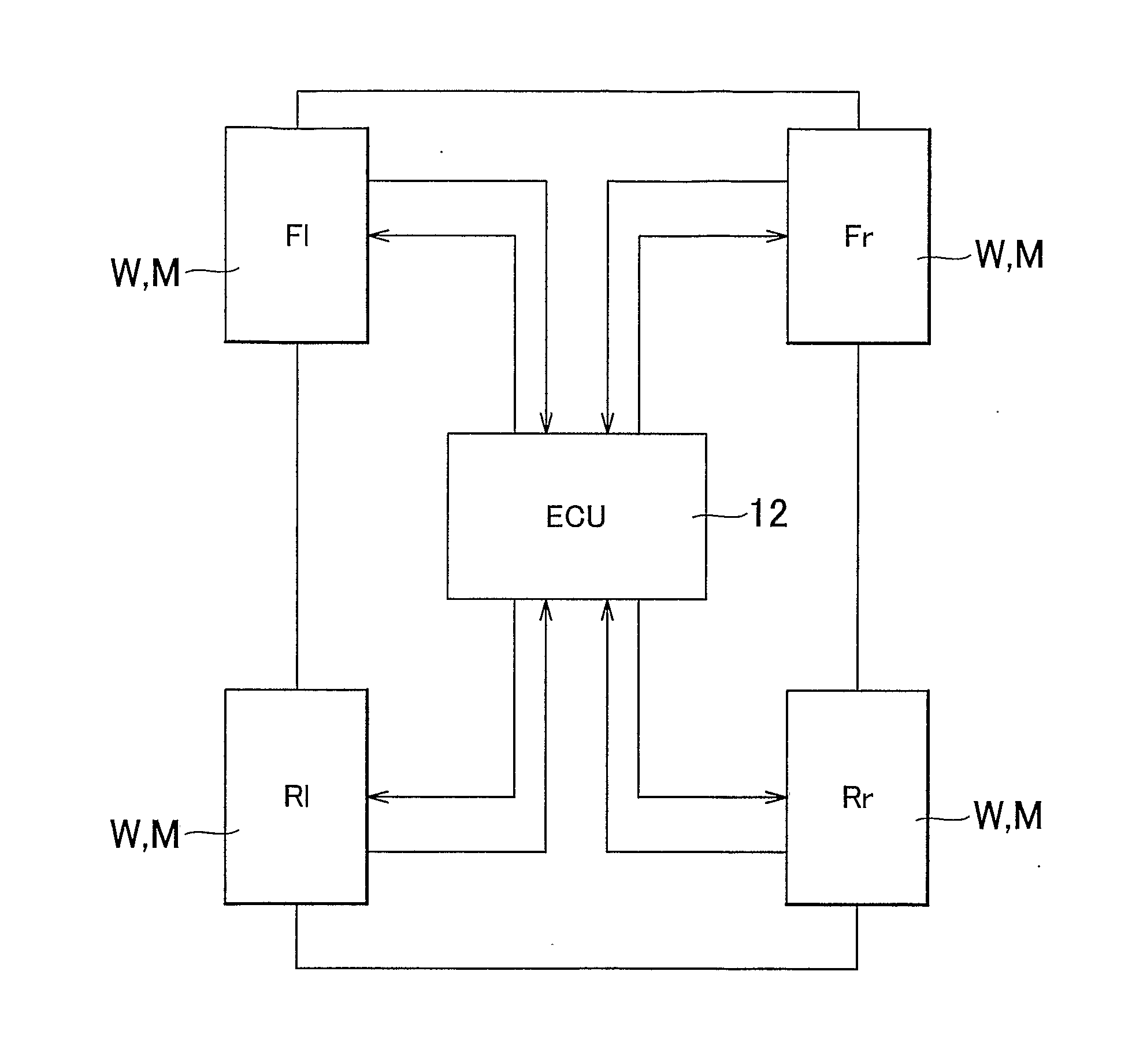
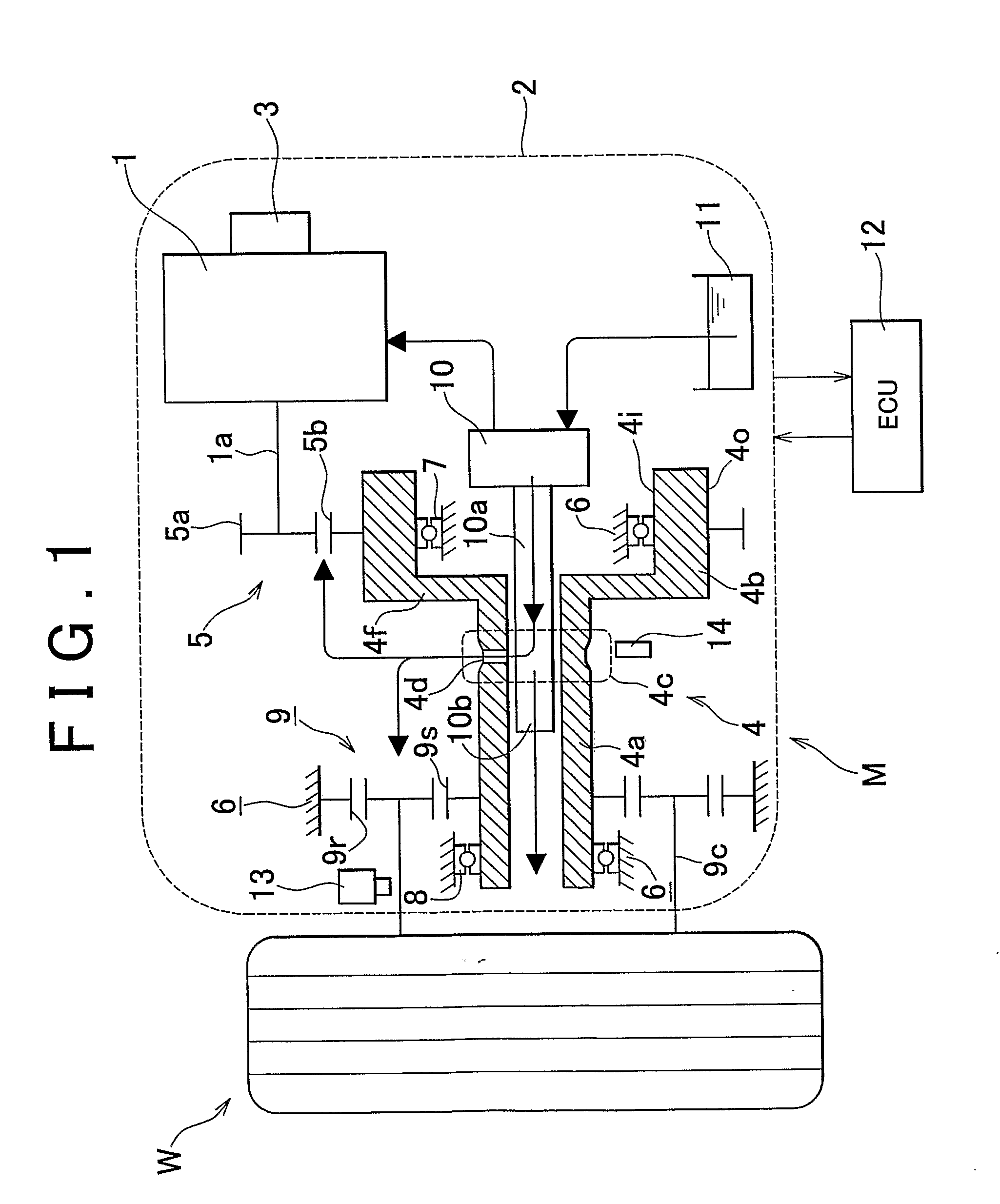
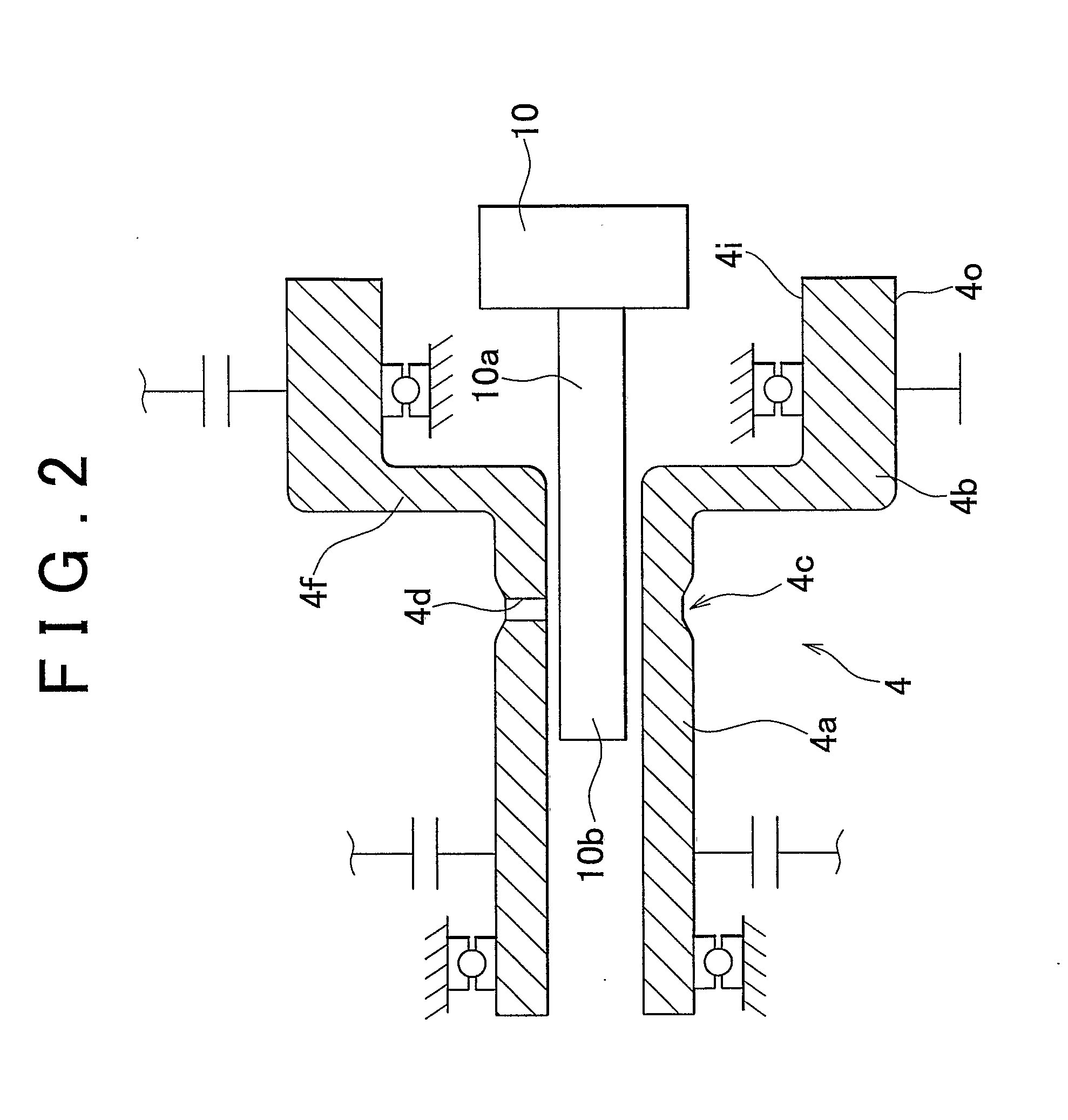
[0051]The drive unit of the invention transmits output torque from a driving power source provided separately for each wheel / tire assembly to each wheel / tire assembly, and generates driving force or braking force in the wheel / tire assembly for which it is provided. One example of such a drive unit is a so-called in-wheel drive unit in which an electric motor (also simply referred to as “motor”) is housed as a driving power source in a wheel of the wheel / tire assembly. The in-wheel motor is an electric motor that is supported by the vehicle body and directly drives the wheel. The in-wheel motor may drive the wheel by having an output shaft that is integrated with a rotor be directly connected to a wheel mount. Alternatively, a speed change mechanism may be interposed between the output shaft and the wheel, and the in-wheel motor may transmit torque that has been increased or decreased by the speed change mechanism to the wheel. This in-wheel motor is supported via an arm member, such...


PUM


Abstract

A drive unit is provided. The drive unit forms a power transmitting path that includes a driving shaft between a wheel/tire assembly and a driving power source provided separately for each wheel/tire assembly, and transmits power via the driving shaft. The drive unit has a weak portion, which is less durable than any other portion in the power transmitting path with respect to external force applied to the wheel/tire assembly, formed on the driving shaft.

Description

BACKGROUND OF THE INVENTION[0001]1. Field of the Invention[0002]The invention relates to a drive unit which is provided for each driving wheel of a vehicle and can apply driving force or braking force by transmitting power directly to the driving wheel for which it is provided, as well as a control apparatus that controls that drive unit.[0003]2. Description of the Related Art[0004]Japanese Patent Application Publication No. 2007-99106 (JP-A-2007-99106) describes one example of a so-called in-wheel motor (IWM) drive unit that has been developed, in which a motor is arranged in or near a wheel of the wheel / tire assembly and is used M directly drive that wheel / tire assembly. The in-wheel motor drive unit described in JP-A-2007-99106 includes a motor, a planetary reduction gear, an output shaft, and a wheel rim. At least one bearing that rotatably supports a rotating element of the planetary reduction gear which is connected to the output shaft is arranged to the inside, in the vehicle...

Claims


Application Information

Patent Timeline
Patent Type & Authority Applications(United States)
IPC IPC(8): B60L15/20B60K17/00
CPCB60K2007/0061B60K17/046F16D9/08B60L2220/46B60K7/0007Y02T10/7258Y10T403/11B60L3/0038B60L3/0061B60L2240/421B60L2240/461Y02T10/64Y02T10/72F16B2200/63
Inventor YOSHIZUE, KENSUKEARAKAWA, KAZUYA
Owner TOYOTA JIDOSHA KK
Why Eureka
Try Eureka