
Desalination device using selective membranes and magnetic fields

a technology of selective membranes and magnetic fields, applied in the direction of seawater treatment, liquid fuel feeders, lorentz force separation, etc., can solve the problem of difficult to obtain a magnetic field with sufficient intensity for the correct desalination of water to be processed

Active Publication Date: 2011-06-23
PENAS BALLESTER PEDRO +1
View PDF4 Cites 11 Cited by
  • Summary
  • Abstract
  • Description
  • Claims
  • Application Information

AI Technical Summary

Benefits of technology

"The present invention is a device that separates ions from water using a magnetic field and an ion-selective membrane. It does not require the use of electrodes or external conducting wires to close the electrical circuit, which reduces the need for energy and eliminates the appearance of redox reactions. The device can be manufactured in prismatic geometries and the separation between membranes is a critical factor for optimal performance. The technical effects of the invention include improved water production levels, energy performance levels, and the effectiveness of the device for saltwater desalination."

Problems solved by technology

Furthermore, the energy that was used in the devices described in the utility models to create an electrical potential that generated electron movement, thus minimising the electrical field, is no longer necessary since said energy was used to neutralise the potential at the ends, but not in the useful movement of the ions.
Obtaining a magnetic field with sufficient intensity for the correct desalination of the water that is to be processed is difficult with permanent magnets, owing to the complex task of magnetising a hollow cylinder by placing one pole on the external face and another on the internal face.

Method used


Image

  • Desalination device using selective membranes and magnetic fields
  • Desalination device using selective membranes and magnetic fields
  • Desalination device using selective membranes and magnetic fields

Examples


Embodiment Construction

[0027]Device that is capable of desalinating part of the salt water flow that enters into it. Therefore, the water that enters into this device is converted into two different effluents. One effluent with a very low concentration of salt that is lower than the intake flow and another with a concentration of salt that is higher than that of the intake flow.

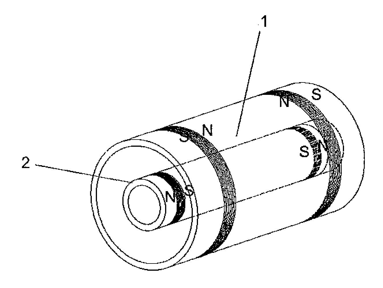
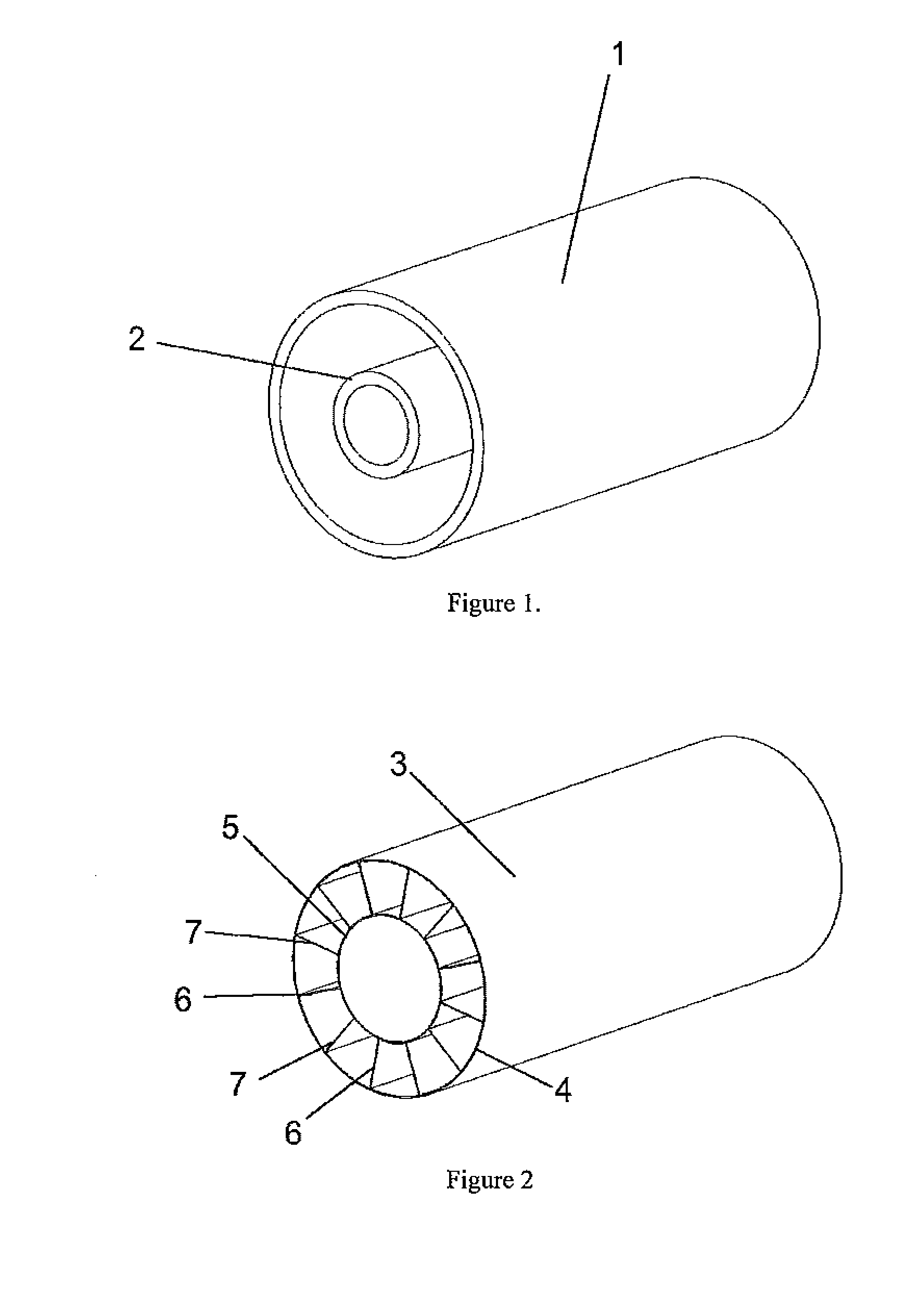
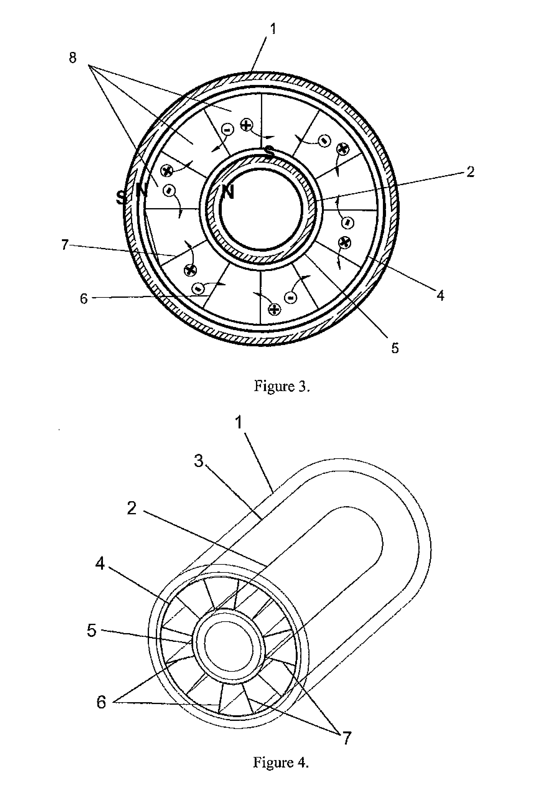
[0028]The device is configured on the basis of three fundamental parts, which comprise an external magnet (preferably a magnetized hollow tubular member of a given diameter), an internal magnet (preferably a magnetized hollow tubular member with smaller diameter than said external magnet) and an intermediate body between said magnets through which the water flow that is to be desalinated passes and which will be affected by the magnetic field generated by the magnets. These three elements will be mounted coaxially. This configuration suggests an optimal form of manufacture based on cylindrical bodies, although the device can also b...


PUM

PropertyMeasurementUnit
internal diameteraaaaaaaaaa

Abstract

Device designed to desalinate brackish water which performs said function by the combined action of magnetic fields generated inside the device and ion-selective membranes, thus obtaining two separate water currents, one with a low salt concentration and the other reject current with a high salt concentration. It comprises an external cylindrical body of magnetized iron (1), an inner body also cylindrical and made of the same material (2) and an intermediate chamber (3) in which are placed a series of ion-selective membranes (6 and 7) arranged radially around the axle common to all of the bodies, and placed alternately such that each negative-ion selective membrane has a positive-ion selective membrane on either side.

Description

BACKGROUND OF THE INVENTION[0001]1. Field of the Invention[0002]The device provides a satisfactory solution for the physical separation of ions dissolved in an aqueous solution from the water molecules of said solution. It has been designed, basically, for the desalination of seawater.[0003]2. Description of the Related Art[0004]The background on selective-membrane desalination devices refers to machines or units that separate the ions dissolved in an aqueous solution using an electrical potential between two electrodes connected to an external power source, i.e. based on electrodialysis. Our desalinisation device does not include electrodes for generating said potential. Thus, it is not based on current concepts of saltwater electrodialysis.[0005]U.S. patent publication No. 2004 / 0262234 discloses an apparatus and method for the purification of fluids and Applicants believe it is the nearest reference to our selective-membrane and magnetic-field desalinisation invention that does no...

Claims


Application Information

Patent Timeline
Patent Type & Authority Applications(United States)
IPC IPC(8): B01D61/14
CPCB01D61/00B01D63/06B01D2311/2607B03C1/0332B03C1/288B03C1/0337C02F1/44C02F1/48C02F2103/08B03C1/023B03C2201/18Y02A20/131
Inventor PENAS BALLESTER, PEDROABAD GARRIDO, FRANCISCO JAVIER
Owner PENAS BALLESTER PEDRO
Learn More