
Sound processing apparatus and method

a technology of sound processing apparatus and sound field, applied in the field of sound field correction technique, can solve problems such as the original sound that has already been decreased, the auditory sensation is affected, and the reverberation remains for a long tim

Inactive Publication Date: 2011-06-23
CANON KK
View PDF15 Cites 51 Cited by
  • Summary
  • Abstract
  • Description
  • Claims
  • Application Information

AI Technical Summary

Benefits of technology

[0010]The present invention reduces the influence of reverberation that occurs after the fall of a signal having a frequency component that causes a standing wave to occur, which is the cause of a problem concerning auditory sensation.

Problems solved by technology

For this reason, the signal component of the dip portion has a lower level while sound is originally produced, and has a higher volume at the time when sound should not be produced, which causes a problem concerning auditory sensation.
Further, a frequency of the standing wave peak portion also has a problem that loud reverberation remains for a long time, for instance.
However, if this technique is applied to the dip portion, negative effects are caused, one example of which is that a portion where the original sound that has already been decreased due to interference is further attenuated, and thus the sound of that portion can hardly be heard.

Method used


Image

  • Sound processing apparatus and method
  • Sound processing apparatus and method
  • Sound processing apparatus and method

Examples


Embodiment Construction

[0023]Hereinafter, a preferred embodiment of the present invention is described in detail with reference to the drawings.

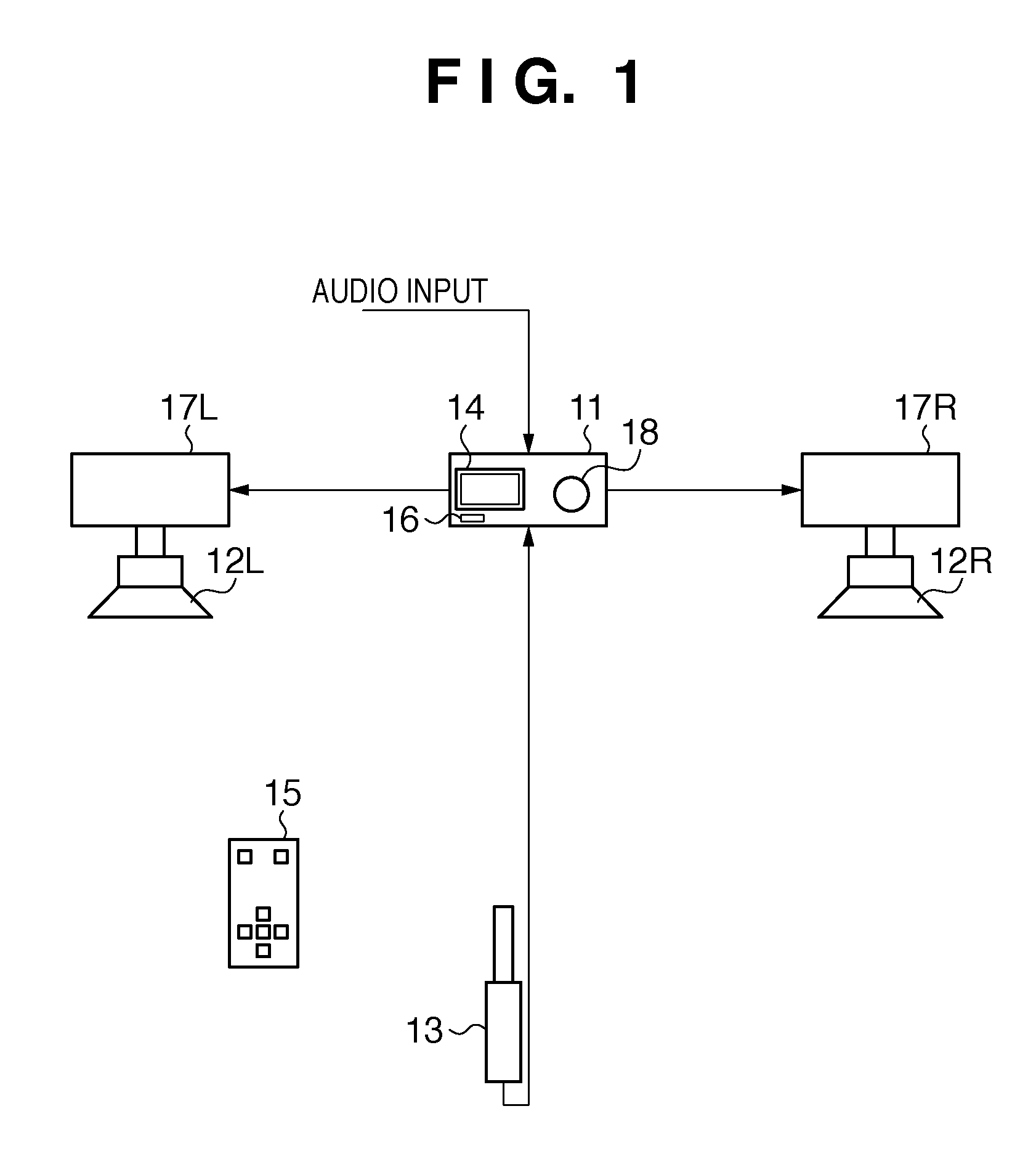
[0024]FIG. 1 is a diagram showing the configuration of a sound system according to an embodiment of the present invention. This sound system can adjust a sound signal to be output based on the acoustic characteristics of a listening room, which is a reproduced sound field, using the configuration and processing that will be described below. A sound processing apparatus 11 is provided with a display unit 14, a volume control 18, a remote controller light receiving unit 16, and the like. Audio signals are transmitted to loudspeakers 12L and 12R from the sound processing apparatus 11. Both of the loudspeakers 12L and 12R are active speakers, and have power amplifiers 17L and 17R, respectively. This configuration is an example, and a configuration may be adopted in which the loudspeakers are not active speakers, and power amplifiers are provided between the sound proc...


PUM


Abstract

A sound processing apparatus according to the present invention acquires a test signal for measuring a standing wave state emitted in a listening room, and determines a peak position or a dip position due to a standing wave based on frequency characteristics of the test signal. Next, the sound processing apparatus emits a burst signal corresponding to the frequency of the peak position or the dip position, and acquires this signal. The sound processing apparatus calculates an increment ΔP of the acquired signal, which indicates an amount of increase of a peak in the trailing edge portion corresponding to the end position of the burst signal relative to a peak in the portion corresponding to the stationary portion of the burst signal, and attenuates the frequency of the above peak position or dip position of a sound signal to be output by an attenuation depending on ΔP.

Description

BACKGROUND OF THE INVENTION[0001]1. Field of the Invention[0002]The present invention relates to sound field correction technique for correcting the influence on frequency characteristics caused by a standing wave in a room.[0003]2. Description of the Related Art[0004]In the case where sound is emitted from a sound source such as a loudspeaker in a room of a house or the like, since there is reflected sound from surfaces such as a wall, a ceiling, and a floor of the room in addition to direct sound that arrives at spots in the room over the shortest distance, these sound waves become superimposed on each other. At this time, for example, a standing wave is generated, and bass resonance called booming occurs between the surfaces facing each other in parallel in the case of a frequency at which the distance between such surfaces is an integral multiple of the half-wave length of the sound wave.[0005]In such a case, booming is suppressed with a parametric equalizer, or acoustic charact...

Claims


Application Information

Patent Timeline
IPC IPC(8): H04R29/00
CPCH04S7/305H04R3/04
Inventor TANAKA, ATSUSHI
Owner CANON KK
Features
  • Generate Ideas
  • Intellectual Property
  • Life Sciences
  • Materials
  • Tech Scout
  • Unparalleled Data Quality
  • Higher Quality Content
  • 60% Fewer Hallucinations
Learn More