
Fan Unit for Filter Fans

a technology of fan unit and fan body, which is applied in the direction of machines/engines, liquid fuel engines, separation processes, etc., can solve the problems of only being able to change the conveying direction, large overall height, and high manufacturing cost, and achieves convenient and cost-effective manufacturing, compact construction, and easy installation of the fan.

Active Publication Date: 2011-06-23
RITTALWERK RUDOLF LOH GMBH & CO KG
View PDF28 Cites 26 Cited by
  • Summary
  • Abstract
  • Description
  • Claims
  • Application Information

AI Technical Summary

Benefits of technology

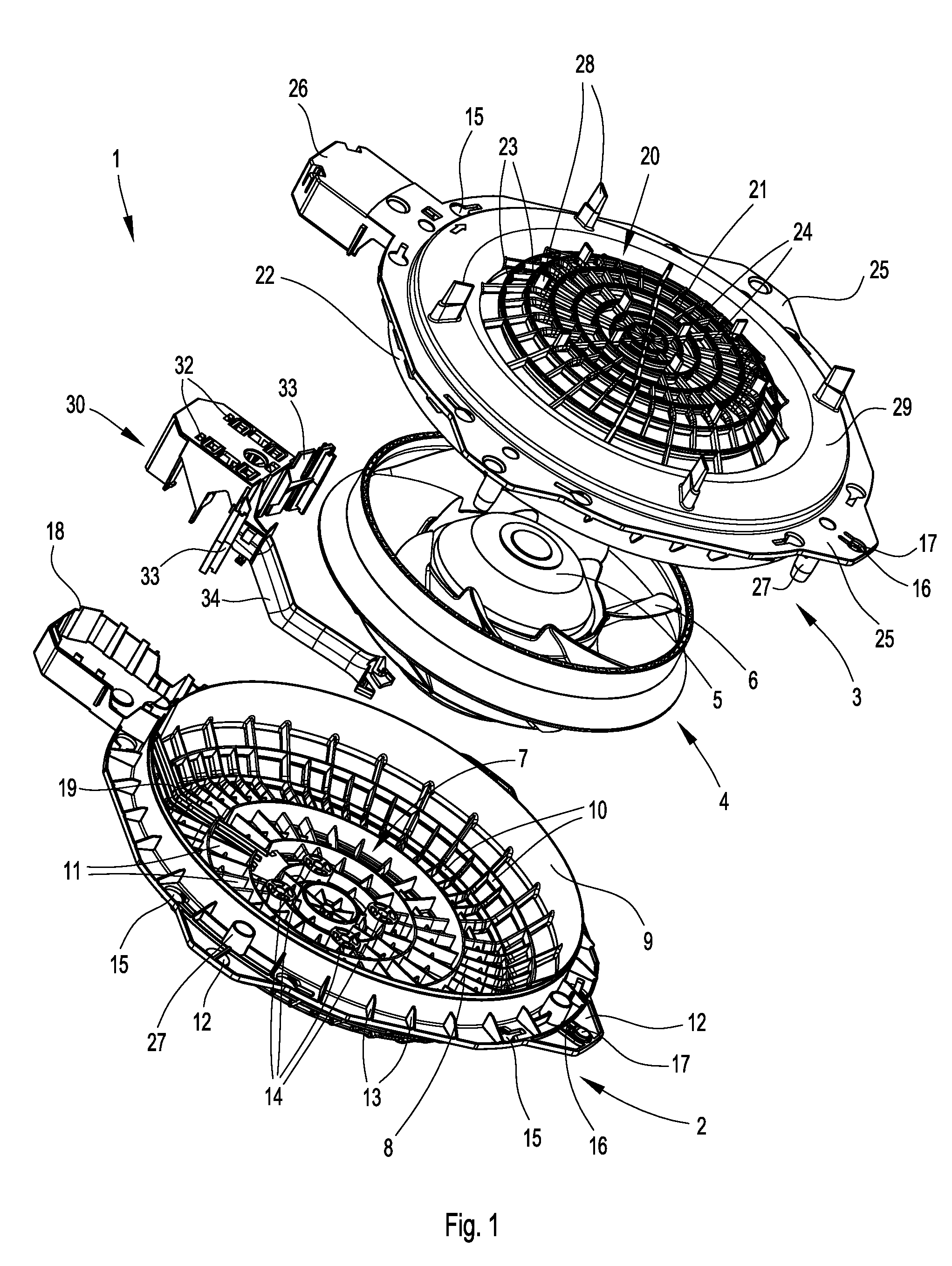
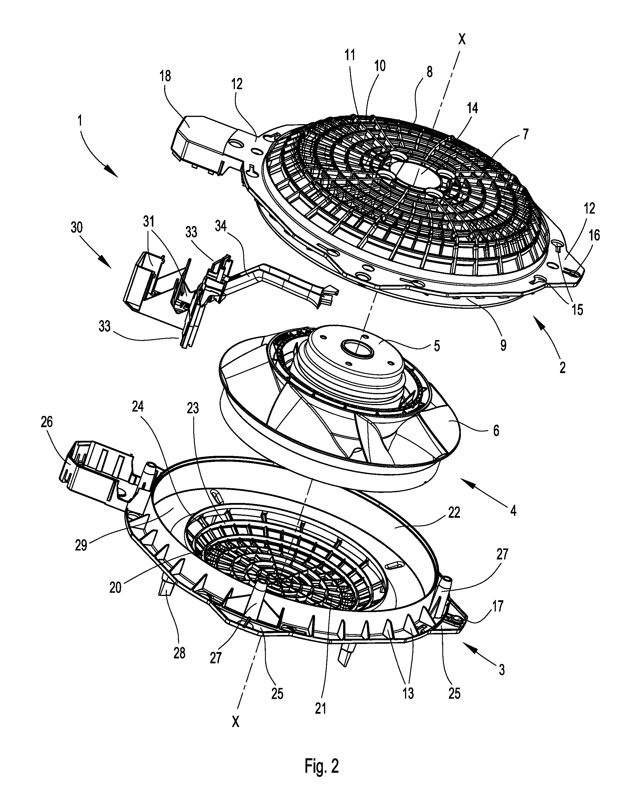
[0005]For a fan unit of the above described type, the object is attained according to the present invention in that the housing is divided perpendicularly with respect to the axis of the fan wheel in the region of the housing rim into at least two housing parts, the motor bracket and the air inlet part, which are connected to one another, whereby the motor bracket as well as the air inlet part each form an integral protective grid structure. It is particularly advantageous if the protective grid structure of the motor bracket has a motor mount with fastening elements for attaching the fan. The division of the housing into two halves together with the integral configuration allows a particularly easy installation of the fan in the fan unit housing. In addition, the housing and the fan unit are thus easy and cost-effective to manufacture, and the fan unit can have a particularly compact construction.
[0007]Furthermore, in one of the embodiments of the invention the fan wheel of the fan is configured as a diagonal fan wheel, and in the outer radial area one or both protective grid structure(s) are configured as outward pointing holding struts inclined obliquely with respect to the axis of the fan, so that one or both protective grid structure(s) are configured in a plate-shape, and the bottom of the plate protrudes outward from the opening of the housing covered by the protective grid structure. In this case, it is particularly advantageous if the diameter of the outflow opening matches the diameter of the housing rim of the motor bracket, and the diameter of the inlet opening is smaller than the diameter of the cylindrical housing rim of the air inlet part. This embodiment has the advantage that a minimum resistance to the air flow is afforded in the outflow direction and / or in the suction direction of the fan, and the air flow and the efficiency of the fan unit are improved.

Problems solved by technology

The disadvantage of such fan units is that they have a large overall height and are expensive to manufacture.
In addition, they have to be mounted on the filter frame in several work steps with tools, and changing the conveying direction is only possible by means of an expensive mounting procedure.

Method used


Image

  • Fan Unit for Filter Fans
  • Fan Unit for Filter Fans
  • Fan Unit for Filter Fans

Examples


Embodiment Construction

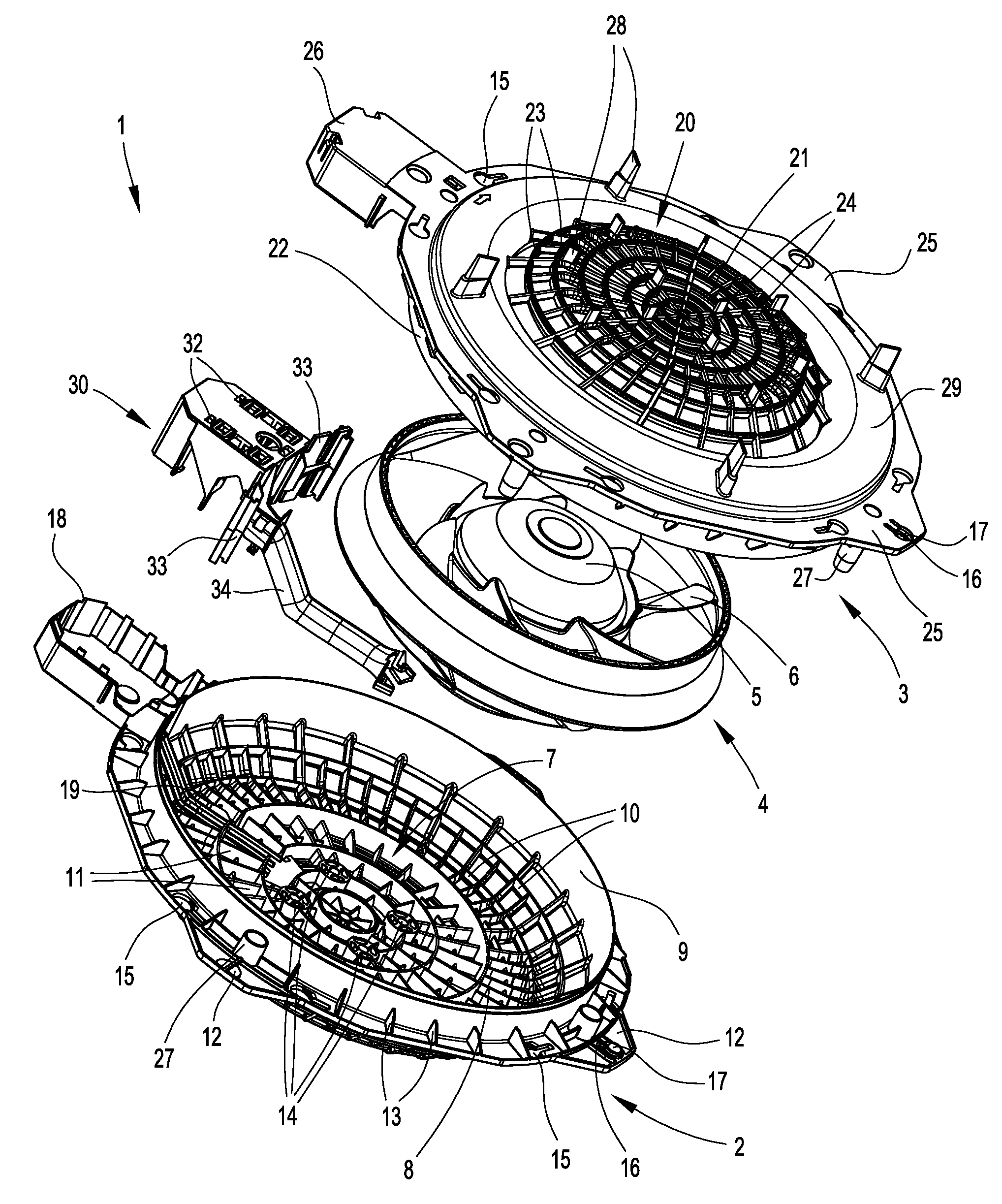
[0017]An embodiment of a fan unit according to the present invention is shown in FIG. 1, FIG. 2, FIG. 3, and FIG. 4. The fan unit 1 has a two-part housing which consists of a motor bracket 2 and an air inlet part 3. A fan 4 is also mounted in the housing. The fan 4 consists of a preferably electronically controlled electric motor 5, in particular of an external rotor motor, with a fan wheel 6 attached to the rotor of the electric motor 5, in particular a diagonal fan wheel or an axial fan wheel.

[0018]The motor bracket 2 is preferably configured as a single part and is preferably made of plastic material. It has an outflow opening 7 which is completely covered by a plate-shaped protective grid structure 8 basically running perpendicularly to the axis X-X of the fan 4. A tubular housing rim 9 joins the edge of the outflow opening 7 forming the lateral wall of the motor bracket 2 and running inward parallel to the axis X-X of the fan 4 in the direction of the air inlet part 3. The diam...


PUM

PropertyMeasurementUnit
Angleaaaaaaaaaa
Efficiencyaaaaaaaaaa
Circumferenceaaaaaaaaaa

Abstract

A fan unit (1), to be attached to a filter frame (40) of a filter fan, consisting of a housing with a cylindrical housing rim, an inlet opening (20), an outflow opening (7) and at least one protective grid which covers one of both of the openings, and one fan (4) attached to the housing via a motor mount (14) which conveys the air in at least the axial direction. The design enabling the manufacture of a more compact fan unit in an easier and more cost-effective manner, which provides high efficiency and can be installed as a suction as well as a blowing fan unit in the filter fan, and is easy to dismount for the maintenance of the filter fan. This is attained in that the fan unit housing is divided perpendicularly with respect to the axis (X-X) of the fan (4) in the region of the housing rim (9, 22) into two housing parts, one forming a motor bracket (2) and the other forming an air inlet part (3), which are detachably connected to one another, whereby the motor bracket (2) as well as the air inlet part (3) each integrally form a protective grid structure (8, 21).

Description

CROSS REFERENCE TO RELATED APPLICATION[0001]This application claims priority to German Patent Application No. DE 20 2009 017 511.1, filed Dec. 22, 2009.FIELD OF THE INVENTION[0002]The invention relates to a fan unit, in particular of type to be attached to a filter frame of a filter fan, consisting of a housing with a cylindrical housing rim, an inlet opening, an outflow opening and at least one protective grid which covers one of both openings, and one fan attached to the housing by means of a motor mount which conveys the air in at least the axial direction.BACKGROUND OF THE INVENTION[0003]Fan units of the above referenced kind are used as a part of a filter fan for industrial installations such as control panels. The fan units can be configured as a blowing fan unit as well as a suction fan unit. The known fan units for fan filters normally have an axial fan wheel as a flow drive of the fan unit and are screwed to the filter frame of the filter fan via a mounting flange of the fa...

Claims


Application Information

Patent Timeline
IPC IPC(8): F04D29/70
CPCB01D46/001B01D2265/022B01D2273/30B01D2279/45F04D25/08H05K7/20181F04D29/646F04D29/701F04D29/703H02B1/565F04D29/526
Inventor HELI, THOMASGUENTHER, JOERGHOFMANN, WALTER
Owner RITTALWERK RUDOLF LOH GMBH & CO KG
Learn More