Battery assemblies

a battery and assembly technology, applied in the field of batteries, can solve the problems of high complexity and power usage of electric systems within automobiles, and high manufacturing and maintenance costs

Active Publication Date: 2011-06-23
GM GLOBAL TECH OPERATIONS LLC
View PDF7 Cites 29 Cited by
  • Summary
  • Abstract
  • Description
  • Claims
  • Application Information

AI Technical Summary

Problems solved by technology

Electrical systems within automobiles, particularly alternative fuel vehicles, such as hybrid, electric, and fuel cell vehicles have advanced in complexity and power usage.
These con

Method used


Image

  • Battery assemblies
  • Battery assemblies
  • Battery assemblies

Examples


Embodiment Construction

[0015]The following detailed description is merely exemplary in nature and is not intended to limit the inventive subject matter or the application and uses of the inventive subject matter. Furthermore, there is no intention to be bound by any expressed or implied theory presented in the preceding technical field, background, brief summary or the following detailed description.

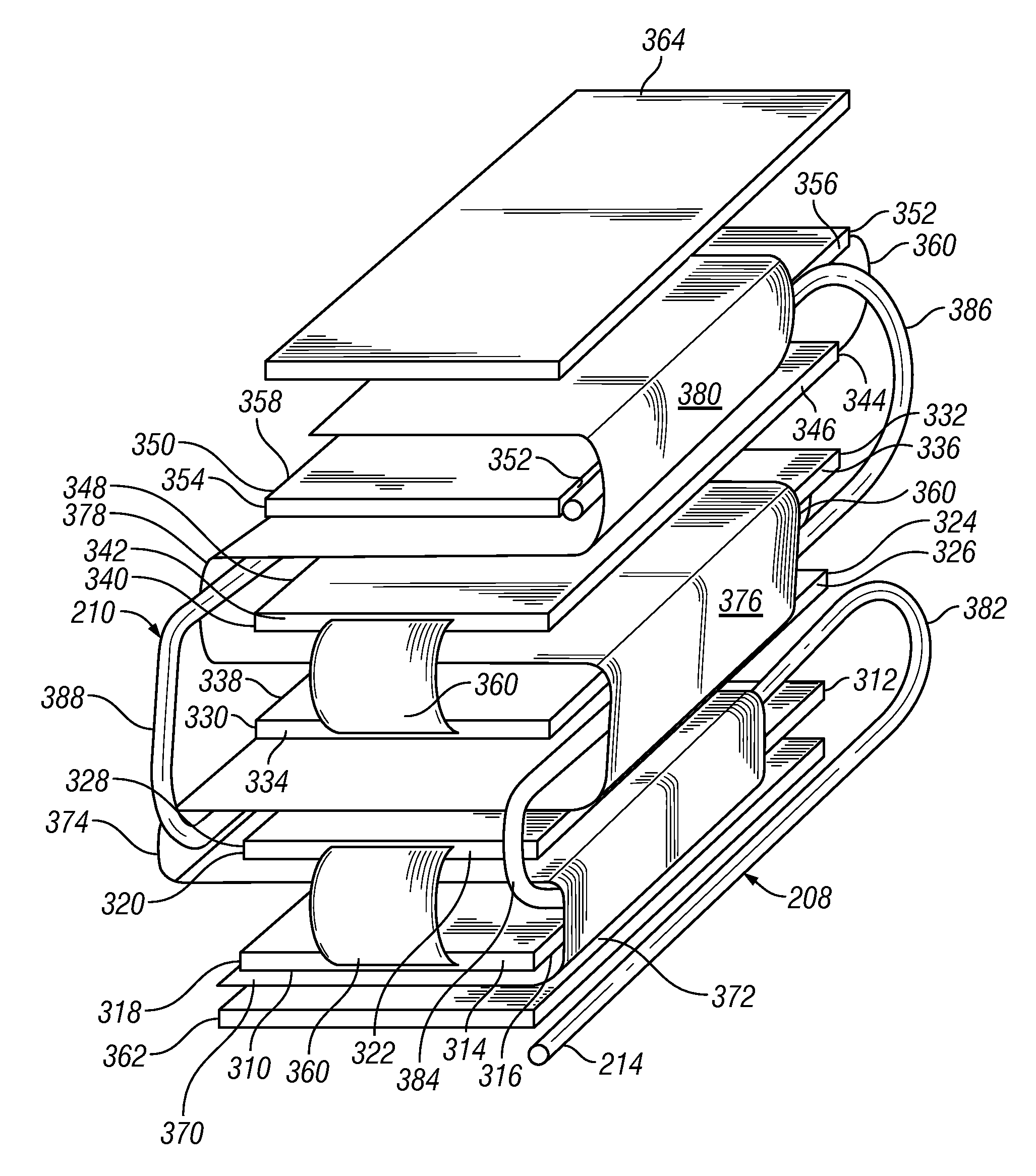
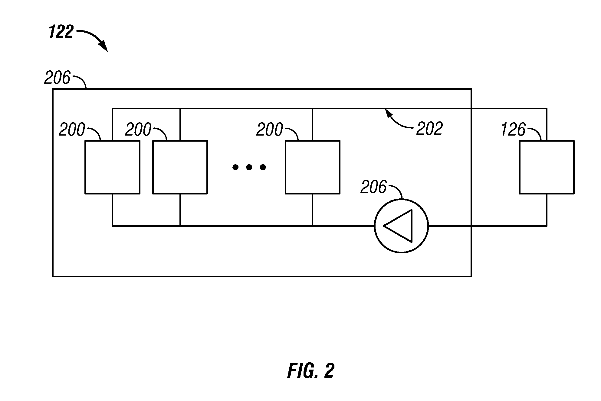
[0016]FIGS. 1 to 6 illustrate automobile and battery assemblies according to exemplary embodiments. Generally, the battery assemblies include one or more battery modules coupled together. Each battery module may include battery unit cells stacked together with a heat transfer layer extending between the battery unit cells. The heat transfer layer is attached to or folds around conduits on the sides of the unit cells. Coolant flowing through the conduits to remove heat generated by the battery unit cells from the heat transfer layer.

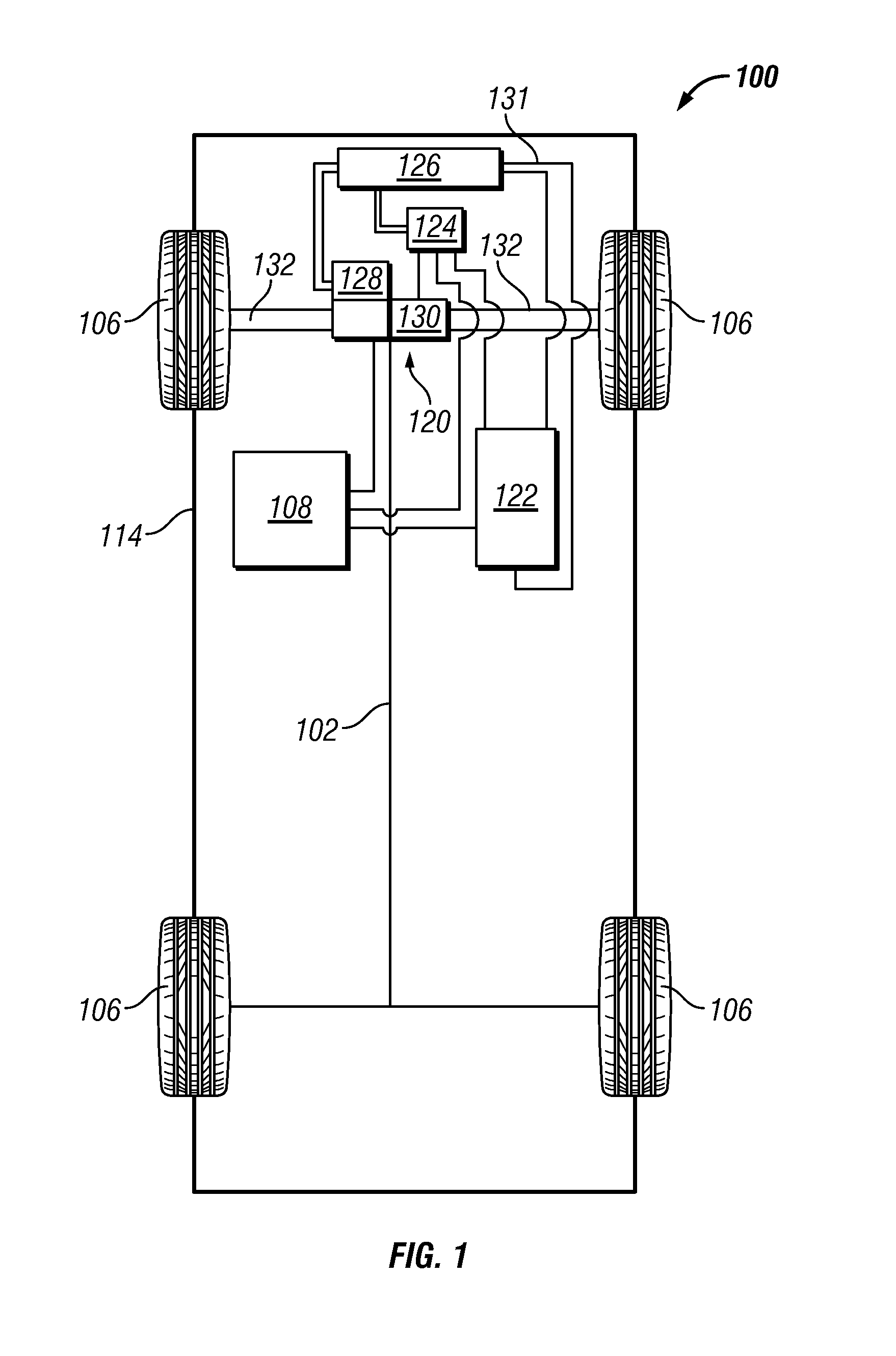
[0017]FIG. 1 is a schematic view of an automobile 100 (or vehicle), according t...


PUM


Abstract

A battery module includes first, second, and third stacked battery cells, the second battery cell being arranged between the first battery cell and the third battery cell. The battery module further includes a first heat transfer layer arranged between the first battery cell and the second battery cell and a second heat transfer layer arranged between the second battery cell and the third battery cell. The battery module may further include a fluid conduit coupled to the first heat transfer layer and the second heat transfer layer.

Description

TECHNICAL FIELD[0001]The inventive subject matter generally relates to batteries, and more particularly relates to battery assemblies for use in automobiles.BACKGROUND[0002]Electrical systems within automobiles, particularly alternative fuel vehicles, such as hybrid, electric, and fuel cell vehicles have advanced in complexity and power usage. Such alternative fuel vehicles typically use an electric motor, in combination with a battery, to drive the wheels of the vehicle.[0003]Alternative fuel vehicles typically use high power output and large capacity batteries as the power source, e.g., a nickel-metal hydride (Ni-MH) battery. In recent years, however, the use of a lithium-ion battery has been attempted. Generally, a number of small-sized lithium-ion unit battery cells are connected in series or parallel with each other so as to construct a larger battery assembly. The battery cells may be prismatic batteries or pouch-shaped batteries that are stacked one on another to reduce dead ...

Claims


Application Information

Patent Timeline
IPC IPC(8): H01M10/50
CPCH01M10/0413H01M10/5004H01M10/5016H01M6/5038H01M10/5055H01M10/5057H01M10/5077H01M10/5032H01M10/625H01M10/647H01M10/6556H01M10/6568H01M10/6555H01M10/613Y02E60/10
Inventor HERRMANN, MANFRED
Owner GM GLOBAL TECH OPERATIONS LLC
Why Eureka
Try Eureka