Electronic booster and operating force transmission device

a technology of operating force transmission and electric booster, which is applied in the direction of braking system, gearing, transportation and packaging, etc., can solve the problems of difficulty in separation from the master cylinder, low degree of freedom in design of electric booster, etc., and achieve the effect of easy separation

Inactive Publication Date: 2011-06-23
HITACHI AUTOMOTIVE SYST LTD
View PDF1 Cites 12 Cited by
  • Summary
  • Abstract
  • Description
  • Claims
  • Application Information

AI Technical Summary

Benefits of technology

[0004]The present invention has an object to provide an electric booster which is structurally easy to be separated from a master cylinder.

Problems solved by technology

However, the electric booster described in Japanese Patent Application Laid-open No. 2007-191133 cited above has a structure in which the hydraulic pressure in the master cylinder is directly received by the input piston, and therefore, is difficult to be separated from the master cylinder.
Hence, the electric booster has a problem of a low degree of freedom in design.

Method used


Image

  • Electronic booster and operating force transmission device
  • Electronic booster and operating force transmission device
  • Electronic booster and operating force transmission device

Examples


first embodiment

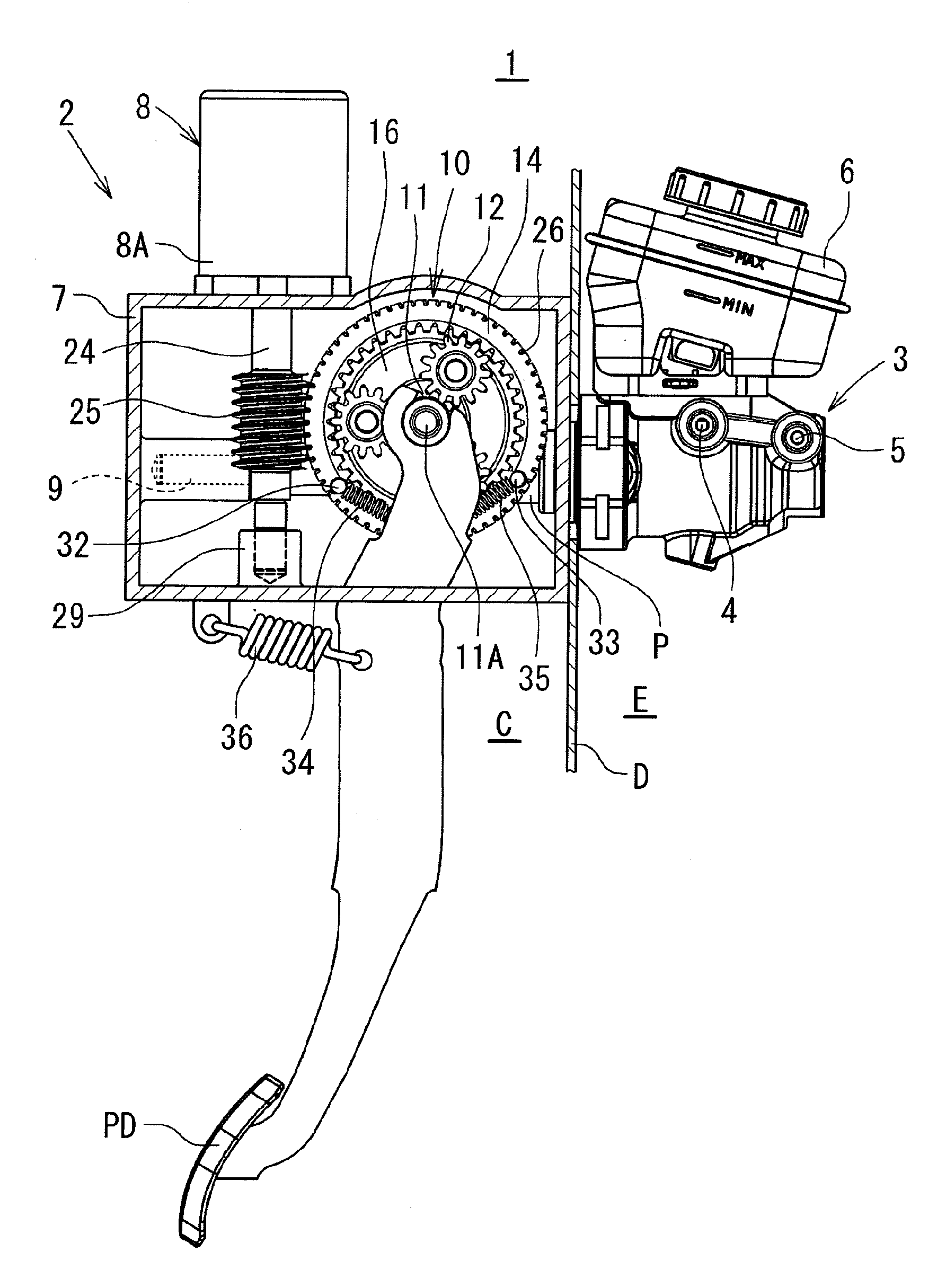
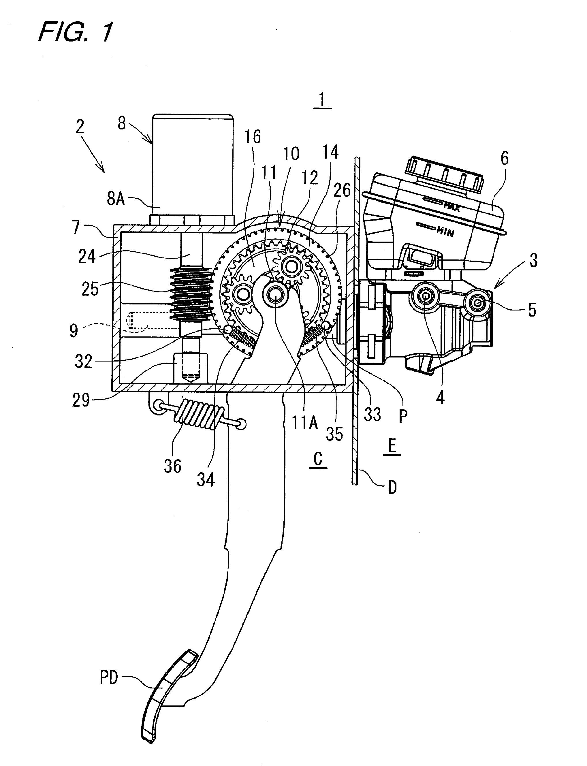
[0025]In the first embodiment, the base portion of the brake pedal PD is directly fixed to be connected to the one end side of the shaft portion 11A. However, other connection structures may be used as long as turning movement of the brake pedal PD is transmitted to the one end side of the shaft portion 11A. For example, the following connection structure may be used. A rotary joint is provided between the one end of the shaft portion 11A and the brake pedal PD so as to enable the rotation of the one end of the shaft portion 11A and the rotation of the base portion of the brake pedal PD relative to each other. In addition, an abutment portion, which comes into abutment against any one of the rotary joint and the one end side of the shaft portion 11A in a direction in which the brake pedal PD is pressed, is provided between the one end of the rotary joint or the shaft portion 11A and the base portion of the brake pedal PD so that the shaft portion 11A follows the turning movement of ...

second embodiment

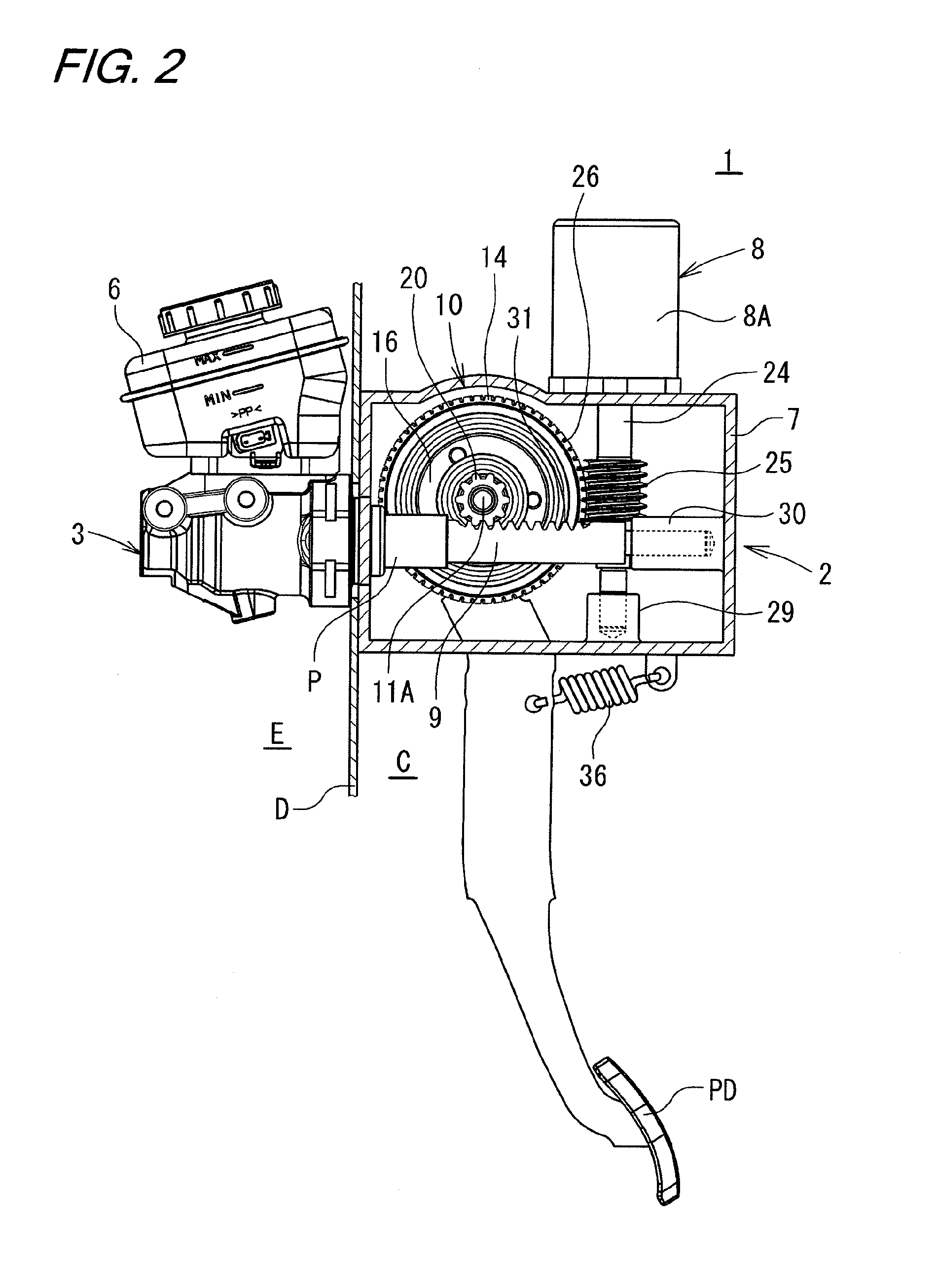
[0056]As the components of the electric booster (1), the planetary gear mechanism is used as the differential transmission mechanism 10 in which the sun gear 11 serves as the first input shaft, the ring gear 14 as the second input shaft, and the planetary carrier 16 as the output shaft. In addition, the external teeth 26 and the worm gear 25 are used as the reduction mechanism, whereas the pinion portion 20 and the rack portion 31 (rack-pinion mechanism) are used as the rotary-to-linear motion converting mechanism. Moreover, in the second embodiment, the external teeth 26 and the pinion 39 (spur gear) are used as the reduction mechanism.

third embodiment

[0057]In the third embodiment described above, the planetary gear mechanism is used as the differential transmission mechanism 10 in which the sun gear 11 serves as the first input shaft, the planetary carrier 16 as the second input shaft, and the ring gear 14 as the output shaft. Moreover, the first planetary gear reduction mechanism 41 and the second planetary gear reduction mechanism 42 are used as the reduction mechanism, whereas the external teeth 26 and the rack portion 31 (rack-pinion mechanism) are used as the rotary-to-linear motion converting mechanism.

[0058]In addition, besides the above-mentioned planetary gear mechanism, for example, a ball reduction mechanism, a wave reduction mechanism or the like can be used as the differential transmission mechanism (10). When the ball reduction mechanism is used as the differential transmission mechanism, a boost ratio equal to that of a barometric booster which is generally mounted on existing vehicles, for example, a reduction ra...


PUM


Abstract

In an electric booster according to one embodiment of the present invention, a brake pedal is connected to a sun gear of a differential transmission mechanism corresponding to a planetary gear mechanism. An electric motor is connected to a ring gear, and an output rod is connected to a planetary carrier, and the output rod is connected to a piston of a master cylinder. When the brake pedal is operated to rotate the sun gear, planetary pinions rotate and revolve around the sun gear. As a result, the planetary carrier rotates to move the output rod forward to push the piston. As a result, a hydraulic pressure is generated in the master cylinder. At this time, the electric motor is controlled according to the rotation of the sun gear to rotate the ring gear so that the ring gear follows the sun gear. In this manner, a servo force of the electric motor is applied to the rotation of the planetary carrier.

Description

BACKGROUND OF THE INVENTION[0001]The present invention relates to an electric booster and an operating force transmission device.[0002]As a booster used for an automobile brake system, there is known an electric booster using an electric motor as a boost source as described in, for example, Japanese Patent Application Laid-open No. 2007-191133. The electric booster drives the electric motor according to movement of an input piston moving in conjunction with an operation of a brake pedal, to thereby thrust a piston of a master cylinder through an intermediation of a ball screw (rotary-to-linear motion converting mechanism). In this manner, the electric booster generates a desired hydraulic pressure and supplies the generated hydraulic pressure to a brake caliper for each wheel. At this time, the hydraulic pressure in the master cylinder is partially received by the input piston which passes through the piston to be inserted into a pressure chamber of the master cylinder. In this mann...

Claims


Application Information

Patent Timeline
Patent Type & Authority Applications(United States)
IPC IPC(8): F16H48/06F16H25/08
CPCB60T13/745B62D5/008Y10T74/18056H01L2924/13091H01L2924/00
Inventor OHNO, TAKAYUKISHIRAKAWA, NAOKIOHTANI, YUKIOUSUI, TAKUYA
Owner HITACHI AUTOMOTIVE SYST LTD
Why Eureka
Try Eureka